Install Steam
login
|
language
简体中文 (Simplified Chinese)
繁體中文 (Traditional Chinese)
日本語 (Japanese)
한국어 (Korean)
ไทย (Thai)
Български (Bulgarian)
Čeština (Czech)
Dansk (Danish)
Deutsch (German)
Español - España (Spanish - Spain)
Español - Latinoamérica (Spanish - Latin America)
Ελληνικά (Greek)
Français (French)
Italiano (Italian)
Bahasa Indonesia (Indonesian)
Magyar (Hungarian)
Nederlands (Dutch)
Norsk (Norwegian)
Polski (Polish)
Português (Portuguese - Portugal)
Português - Brasil (Portuguese - Brazil)
Română (Romanian)
Русский (Russian)
Suomi (Finnish)
Svenska (Swedish)
Türkçe (Turkish)
Tiếng Việt (Vietnamese)
Українська (Ukrainian)
Report a translation problem


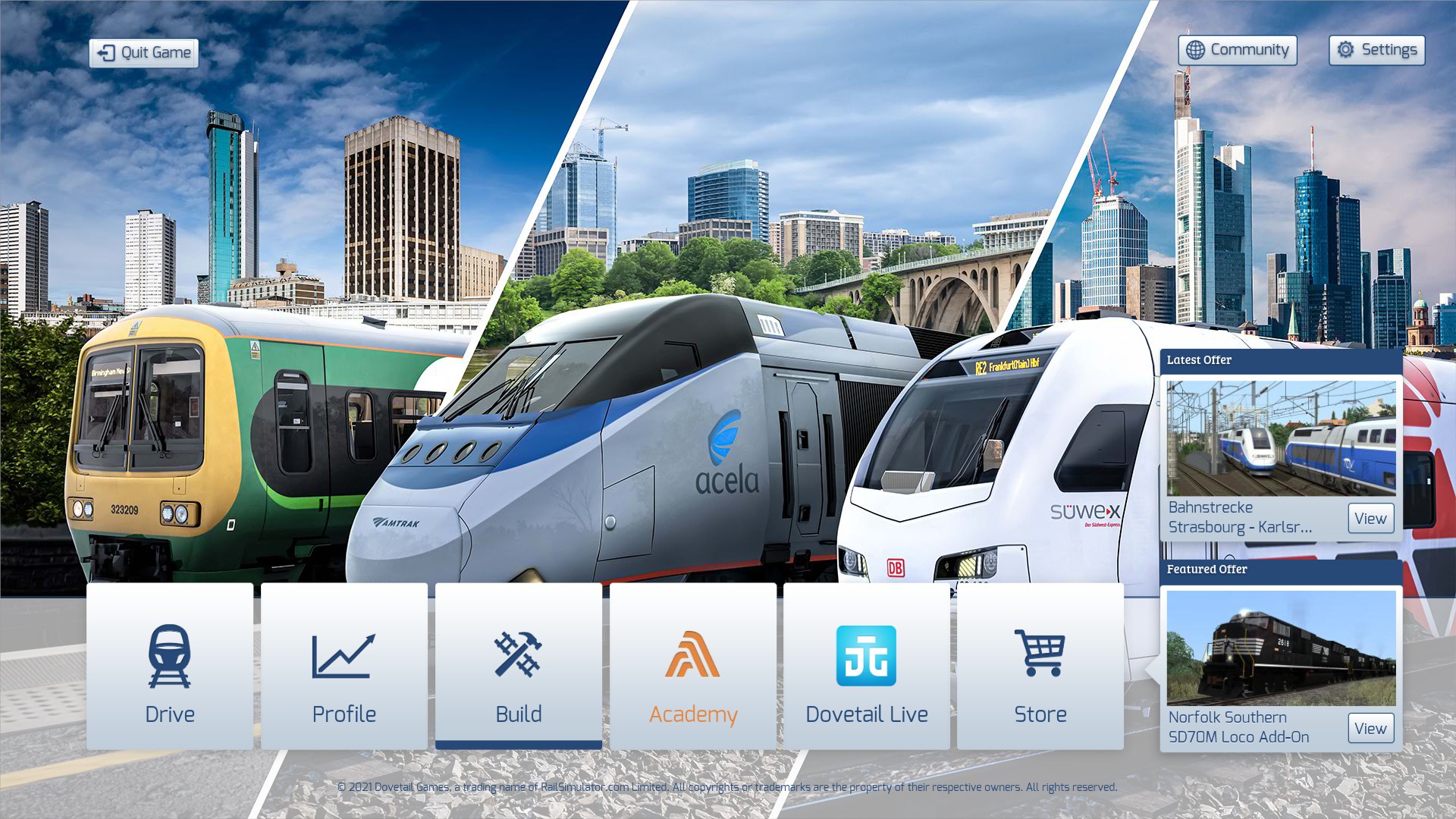
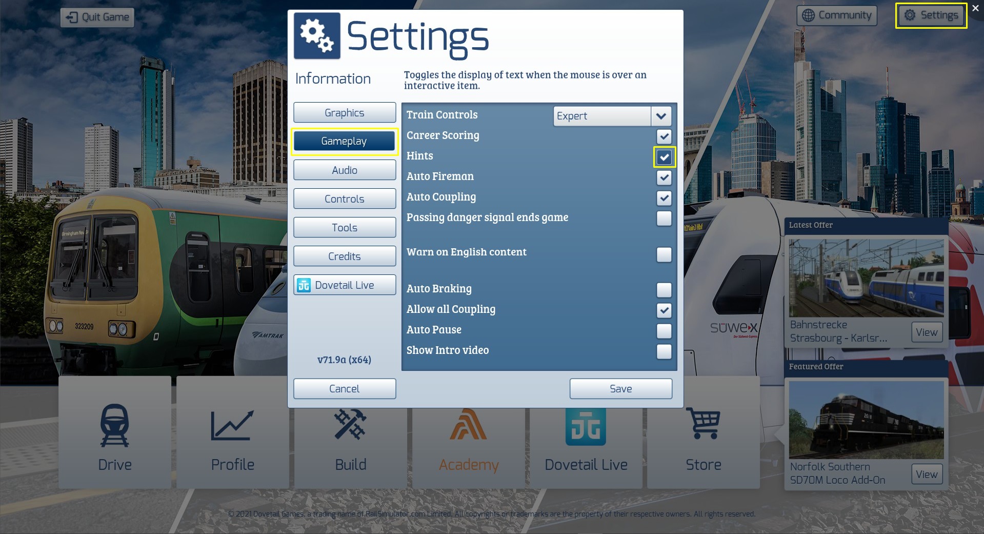
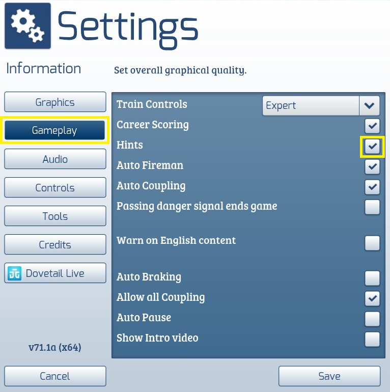


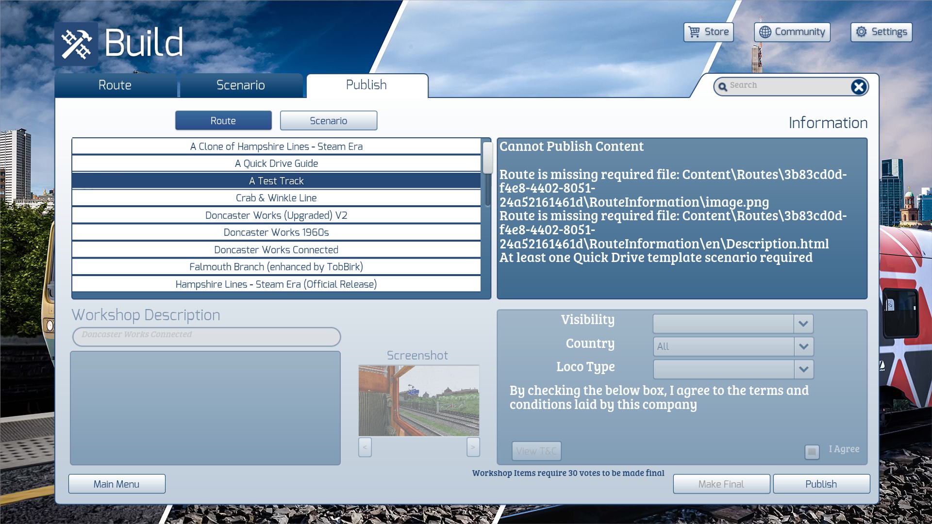


1. Open the Scenario Editor : Start by opening the Scenario Editor in Train Simulator Classic.
2. Select the Scenario : Choose the scenario you want to edit.
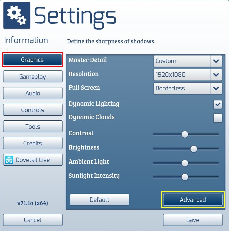
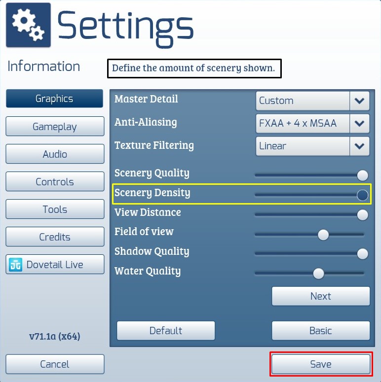
3. Weather Settings : Look for the weather settings option. This is usually found in the scenario properties or environment settings.
4. Choose Weather Type : Select the weather type you want to change to. In this case, choose "Rain" or a similar option.
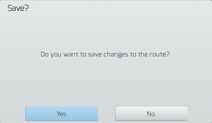
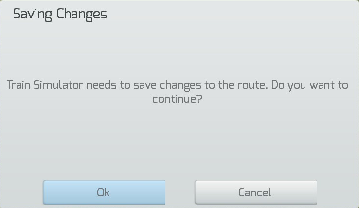
5. Save Changes : Save the changes to your scenario.
Using Direct File Editing to add electrification is not practicable. You would need to edit the Tracks.bin file and add specific information for each section of track.
<Network-cTrackNetworkElectrification d:id="187920006">
<_start d:type="sFloat32" d:alt_encoding="0000000000000000" d:precision="string">0</_start>
<_end d:type="sFloat32" d:alt_encoding="000000C0C8CE4540" d:precision="string">43.6155</_end>
<ScenarioOwned d:type="bool">1</ScenarioOwned>
<Property>
<Network-iTrackNetworkElectrification-cPropertyValue>
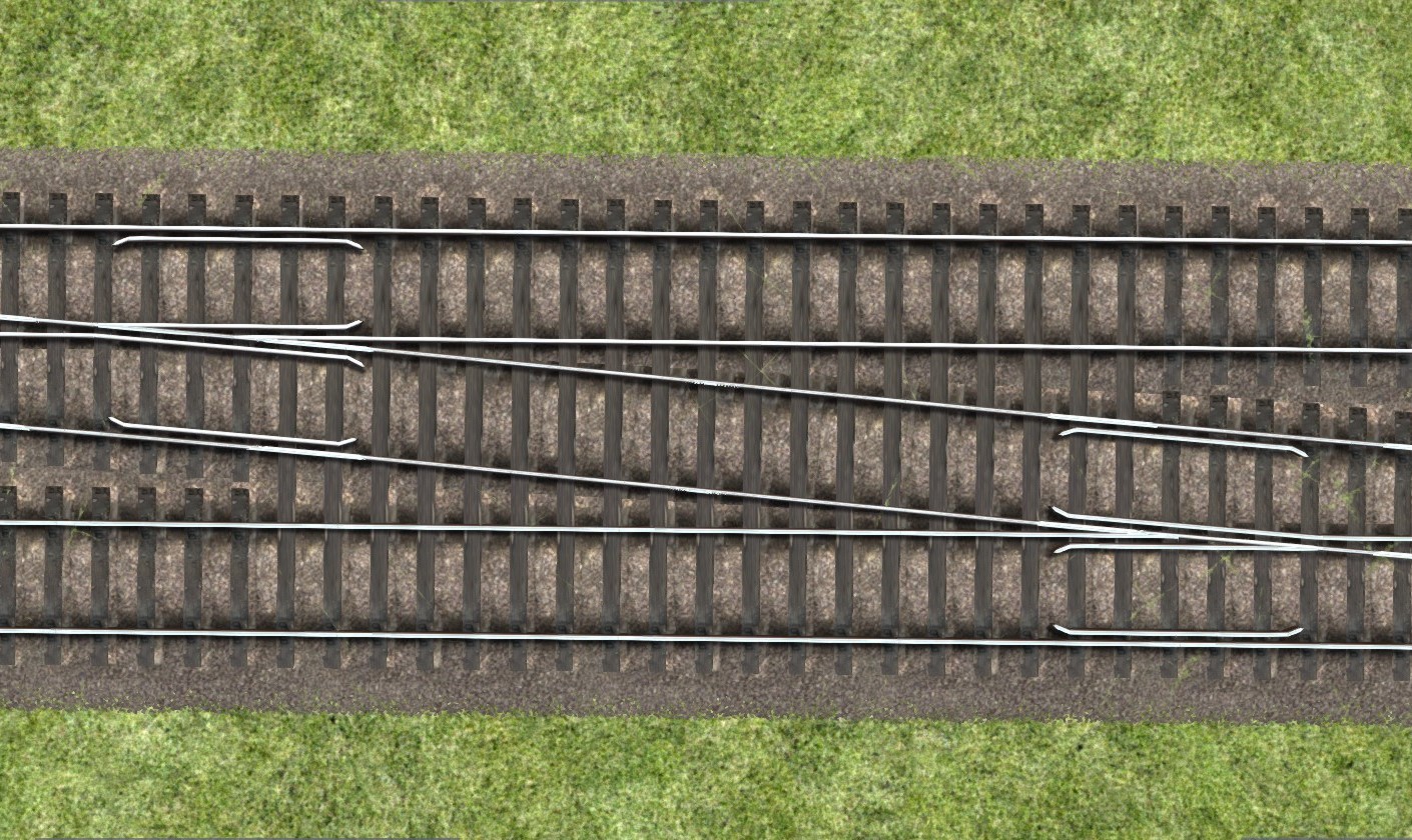
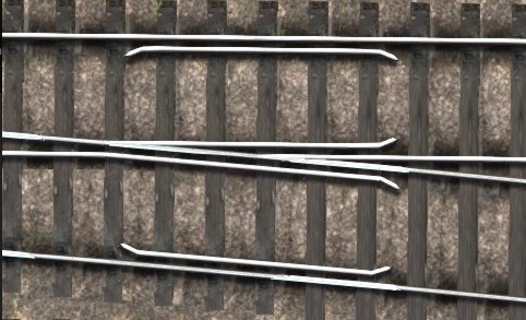
<Electrification d:type="cDeltaString">ThirdRail</Electrification>
</Network-iTrackNetworkElectrification-cPropertyValue>
</Property>
</Network-cTrackNetworkElectrification>
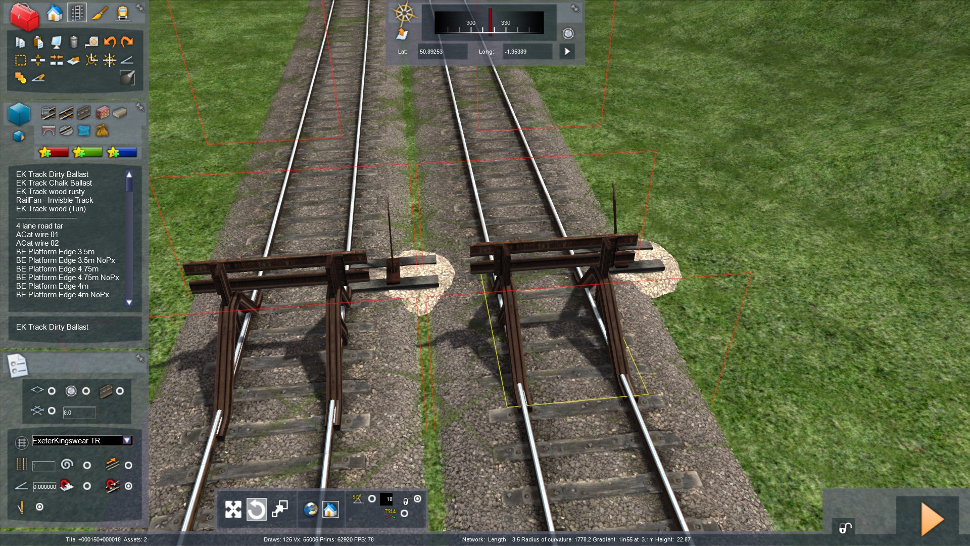
This would need to contain info about the position of the section of track and the length involved.
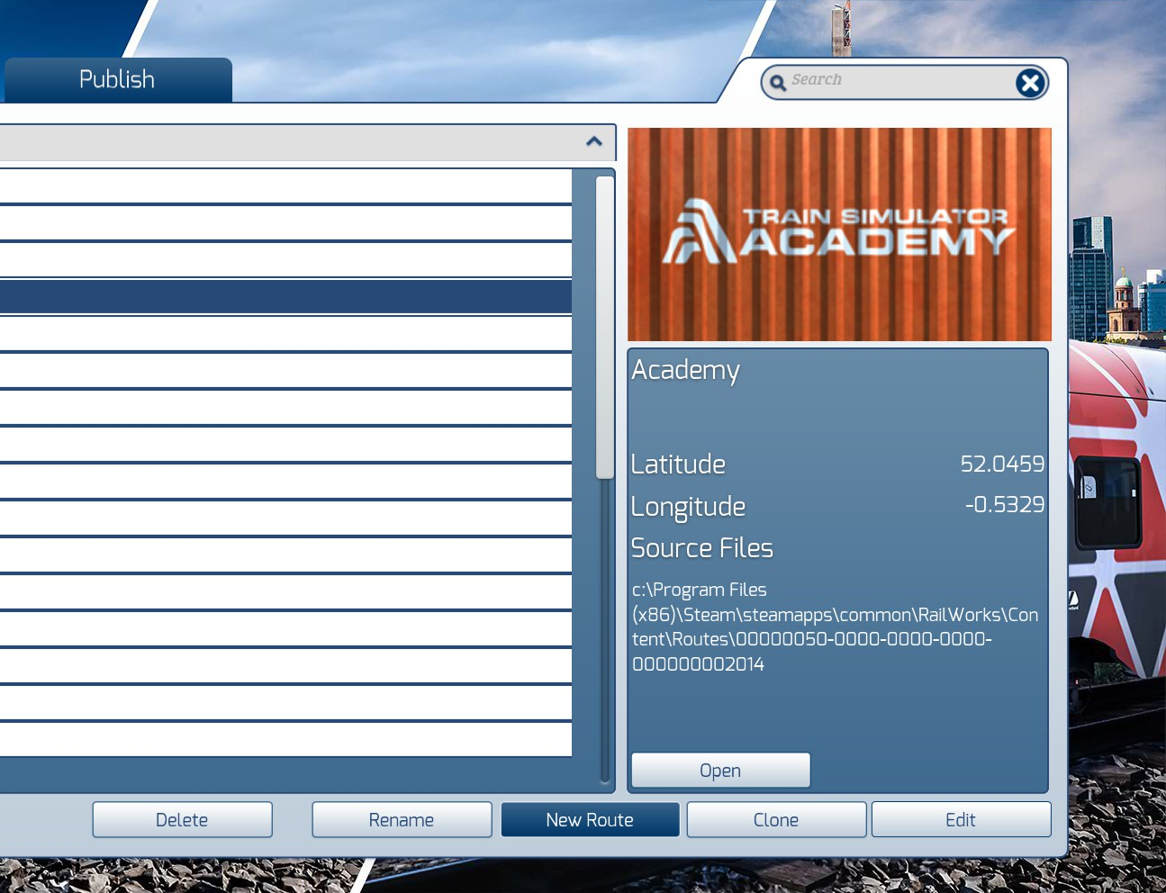
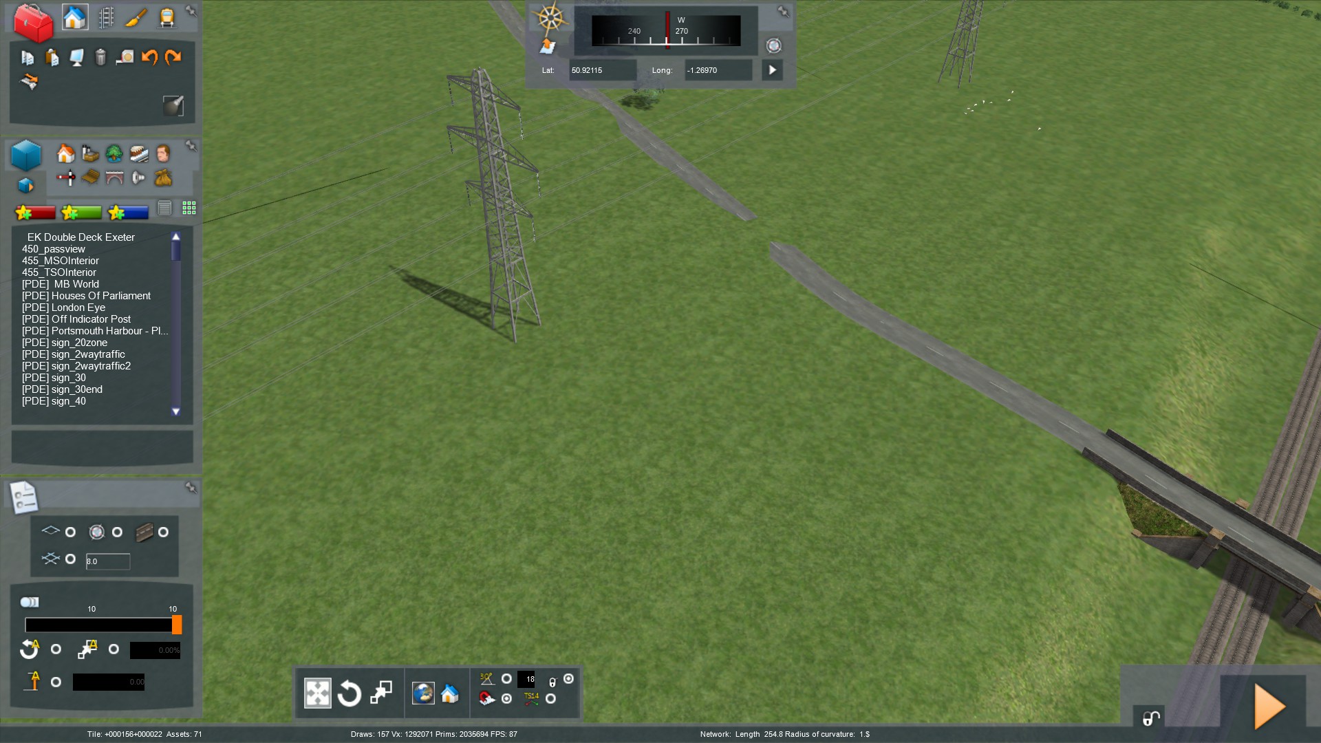
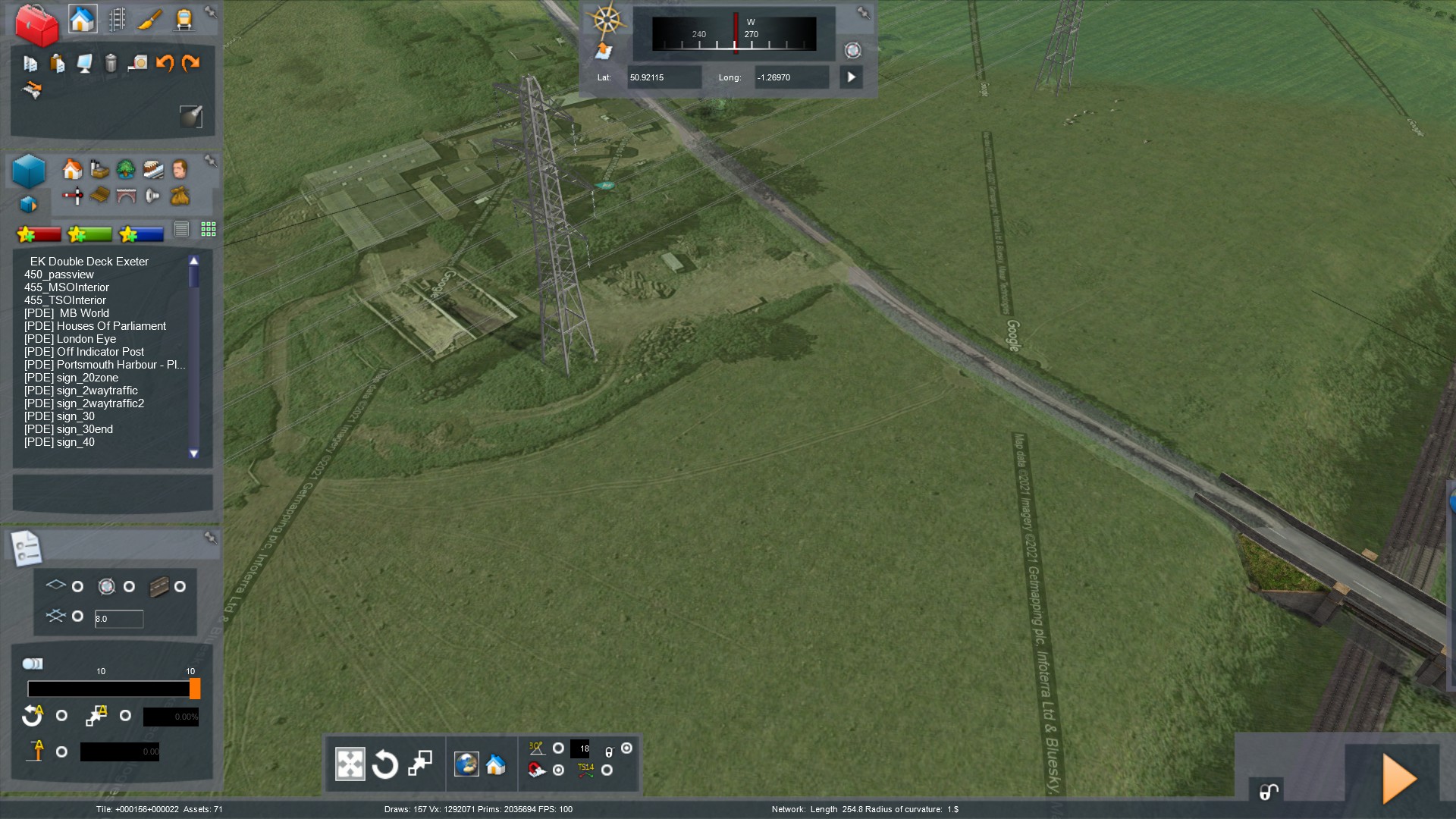
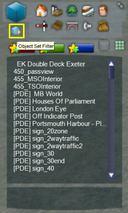
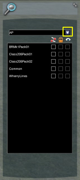
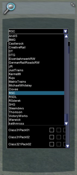
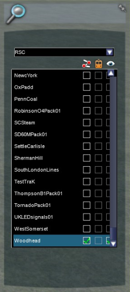
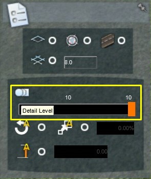
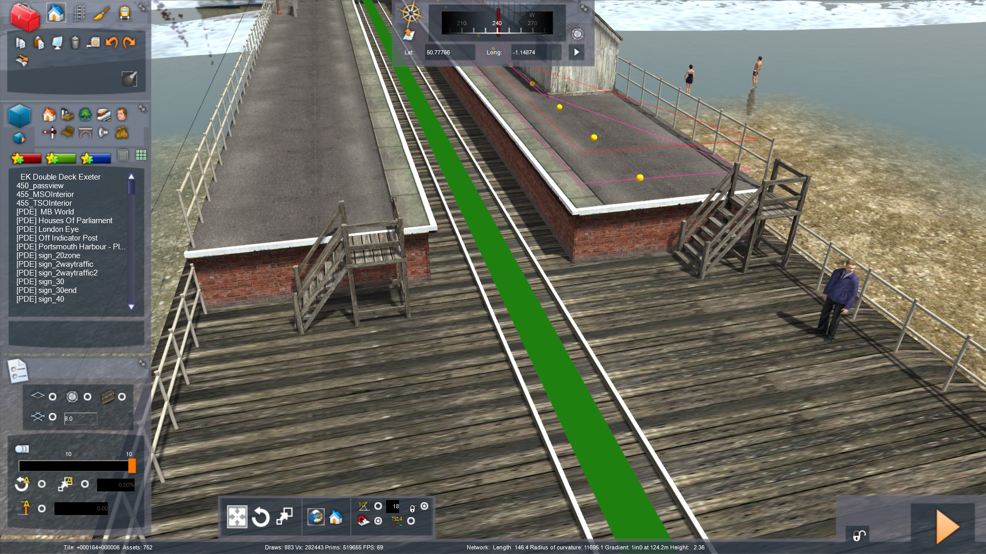
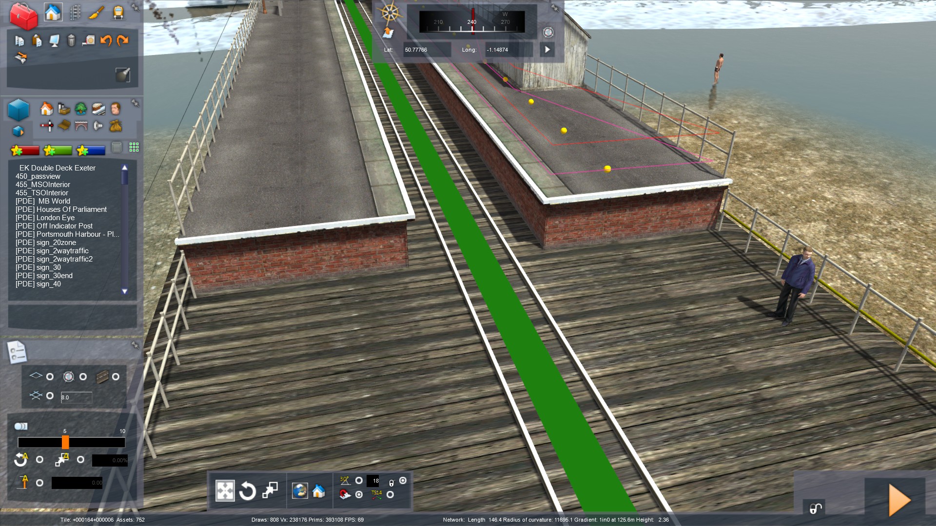
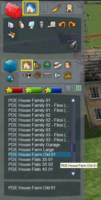
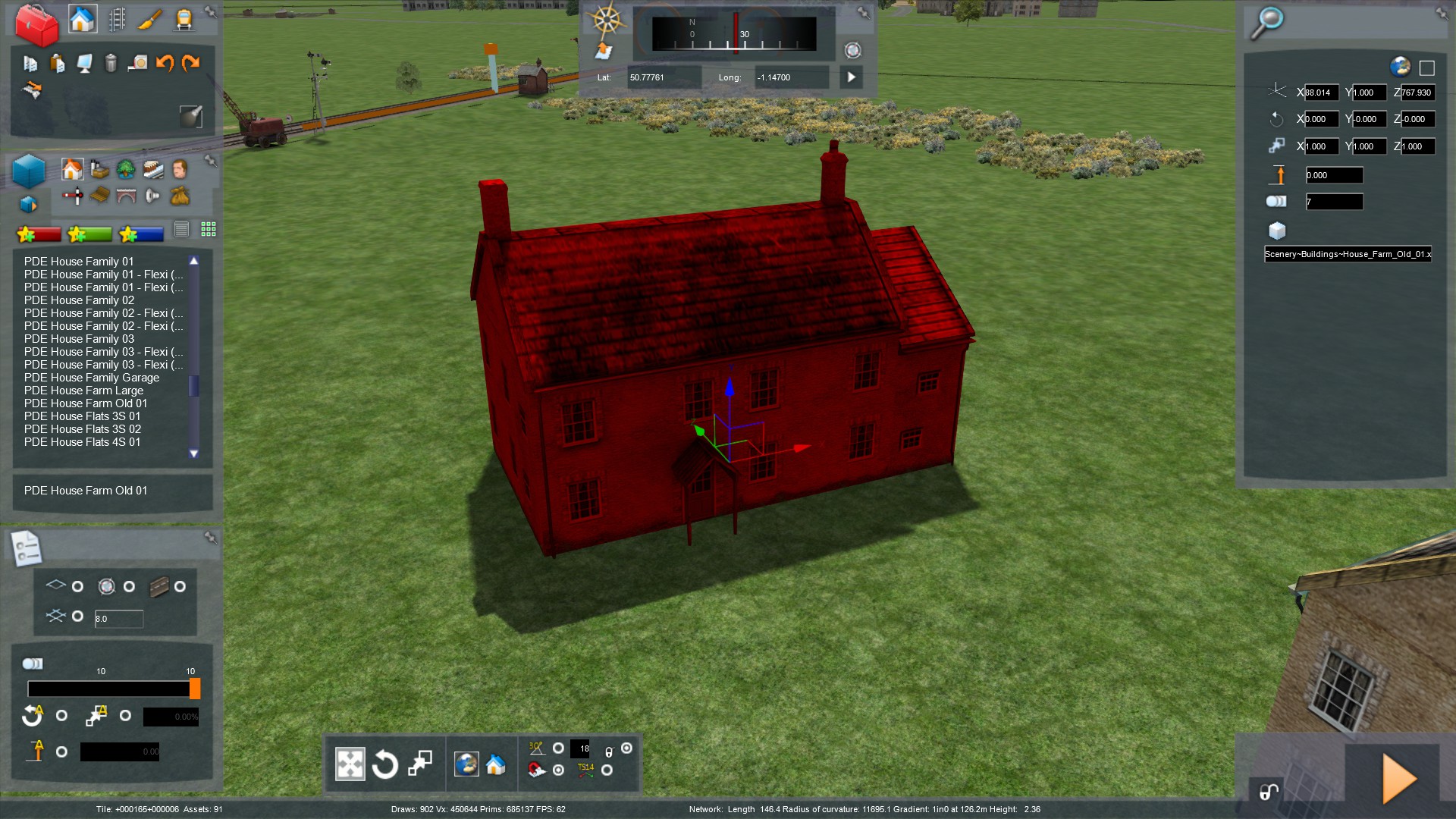
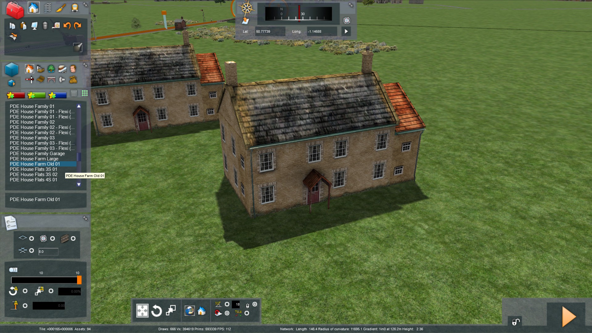
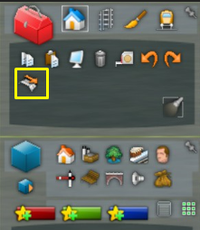
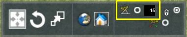
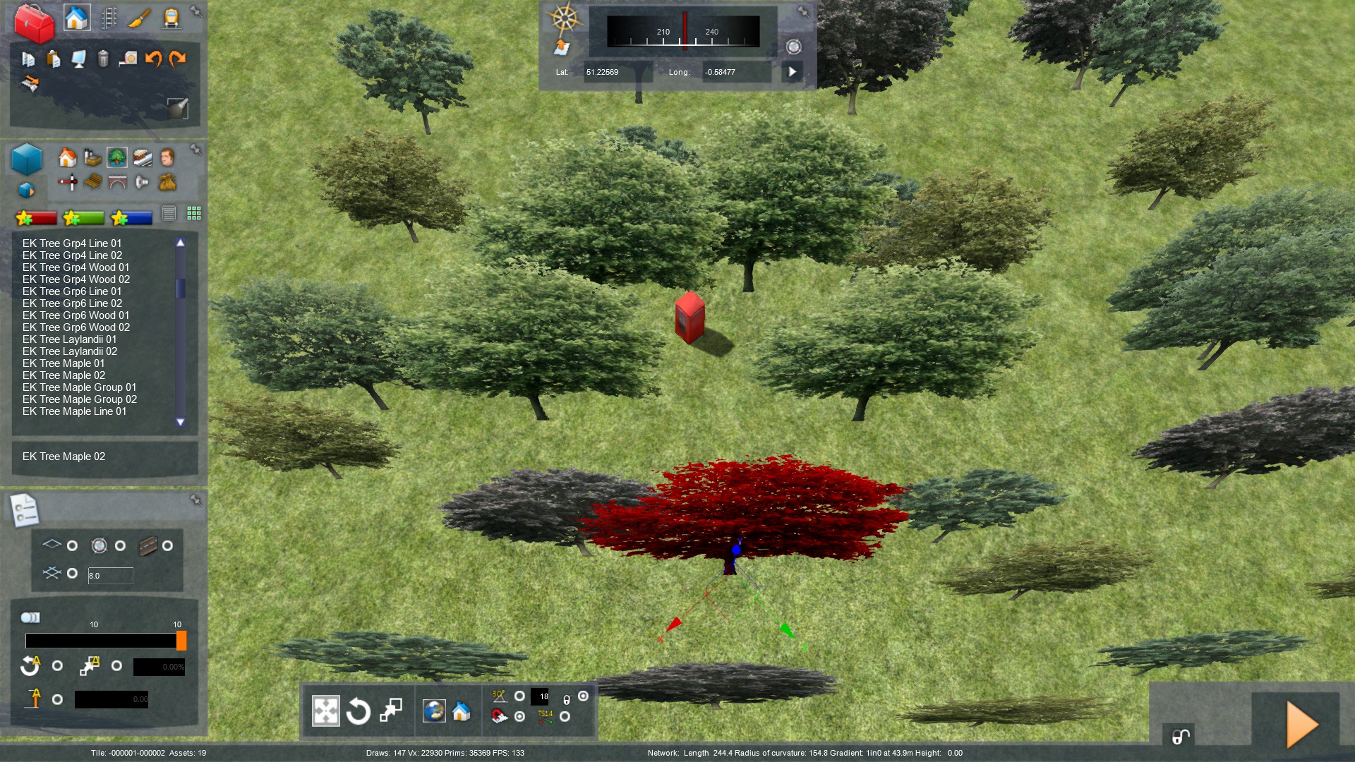
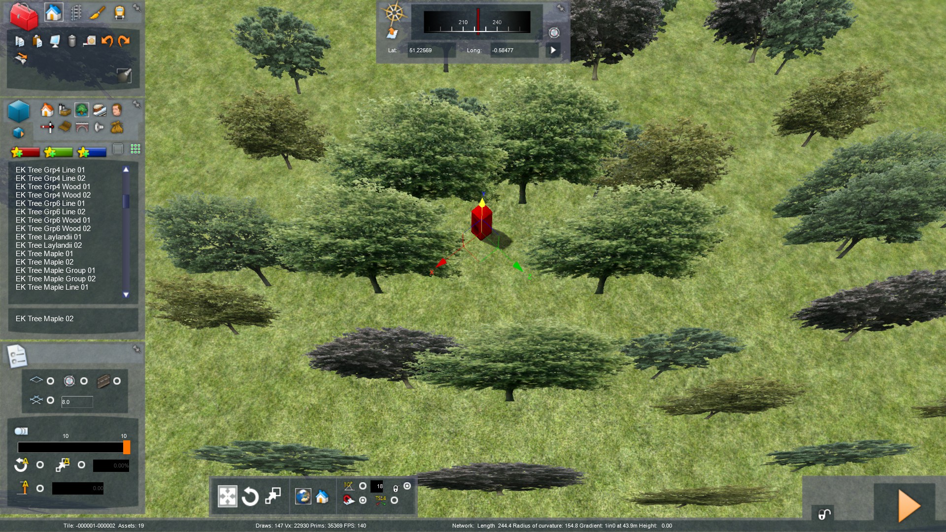
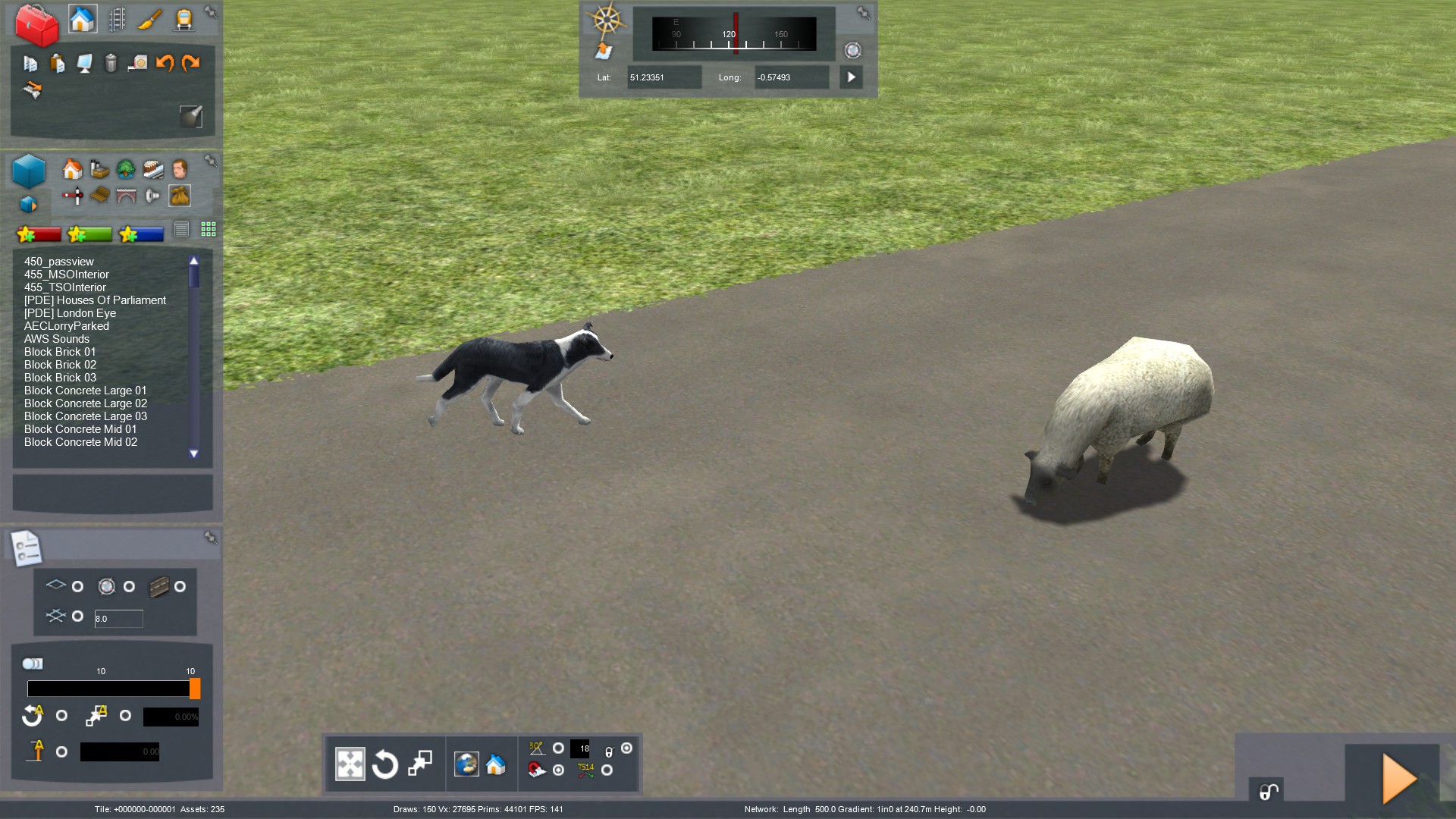
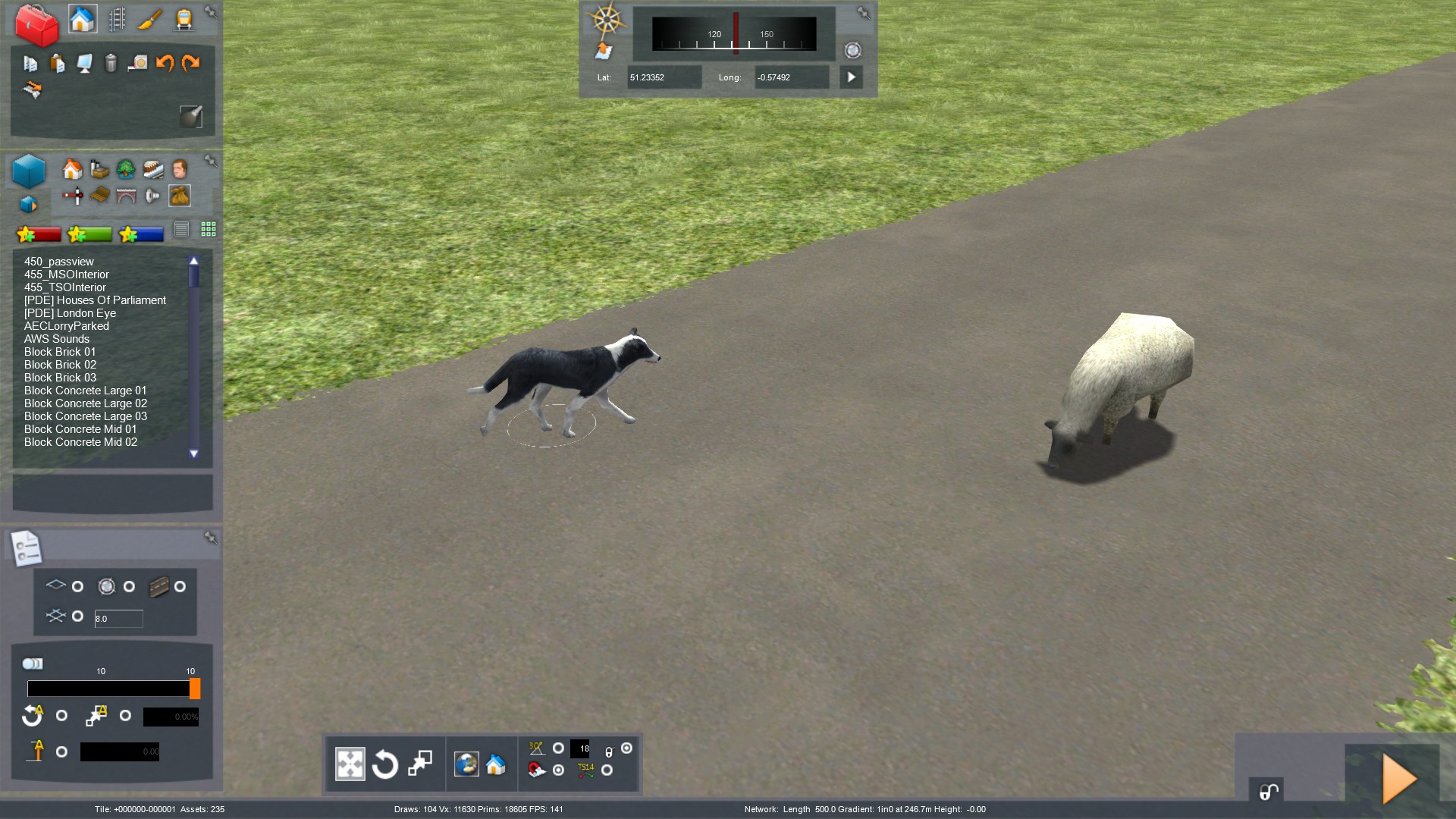
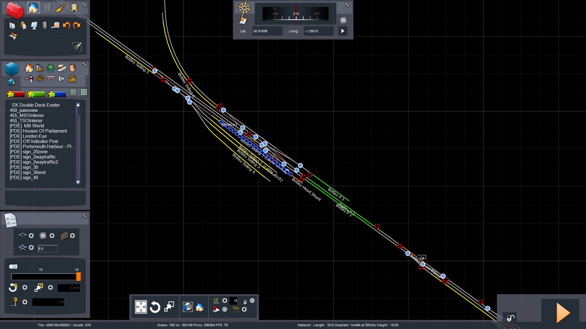
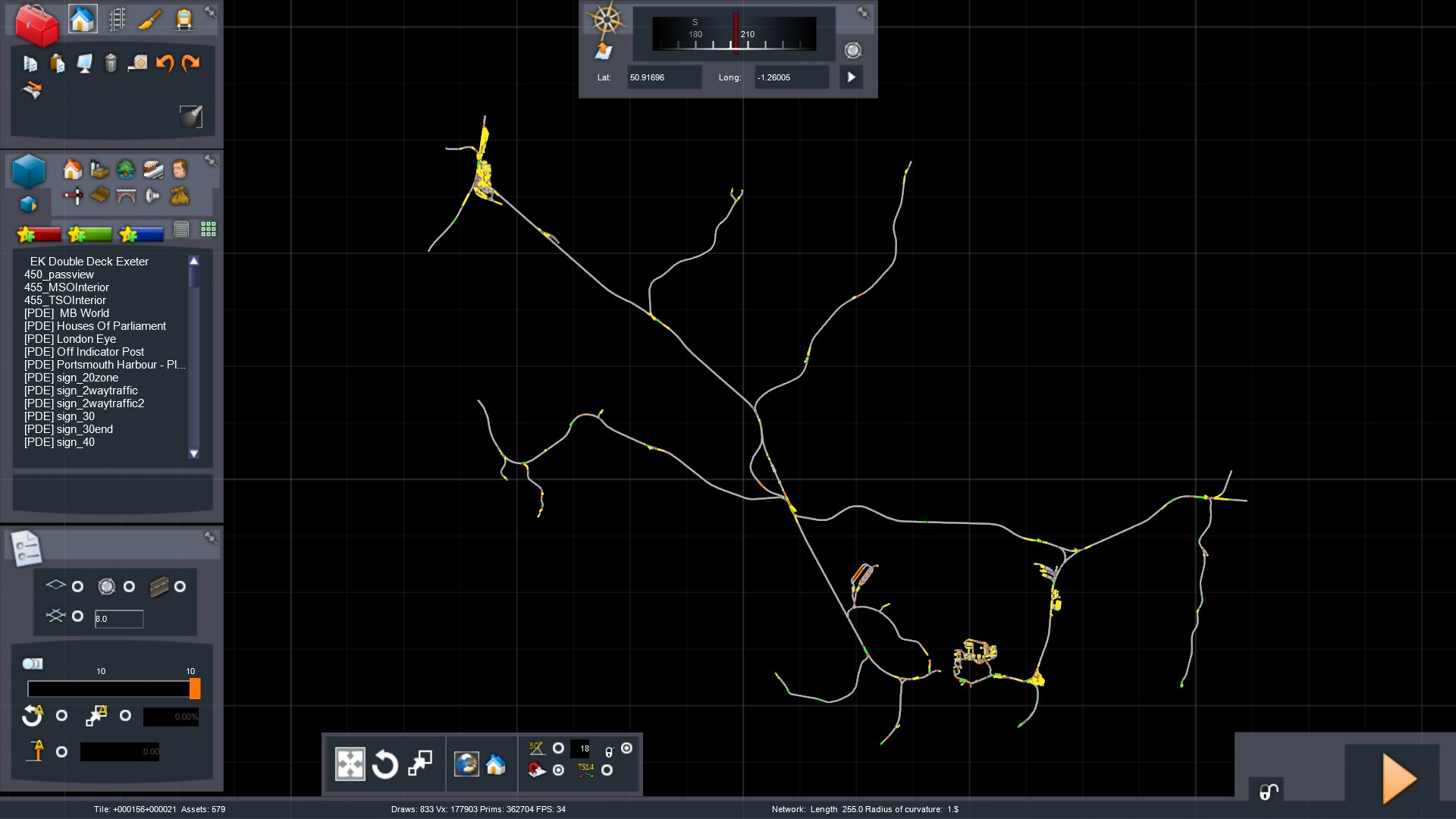
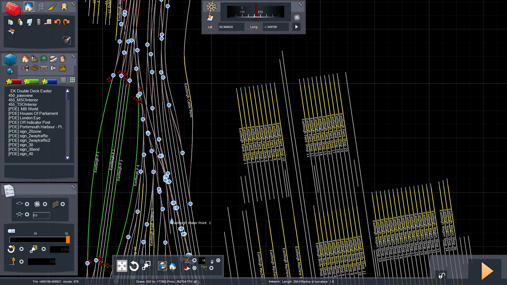
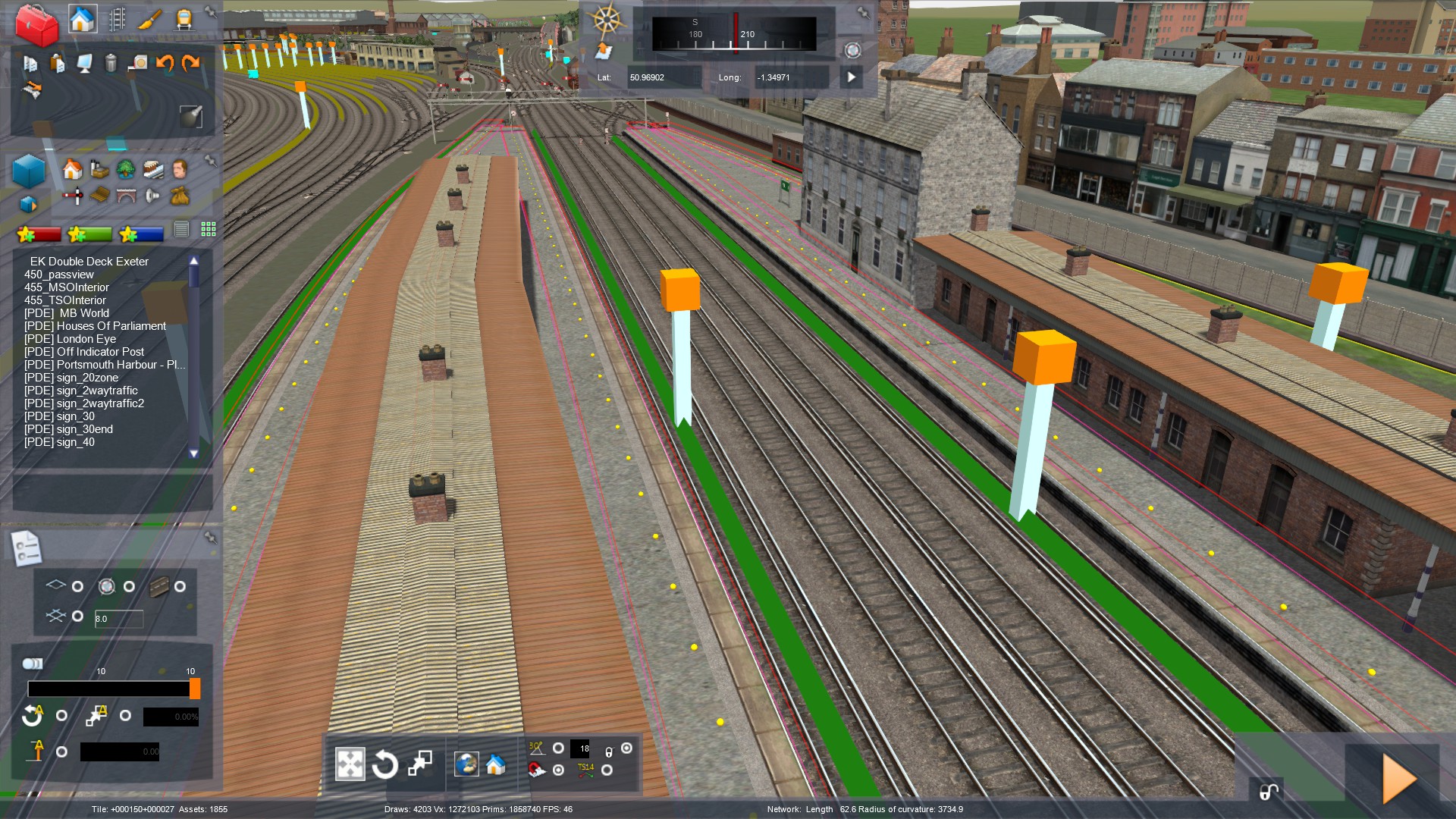
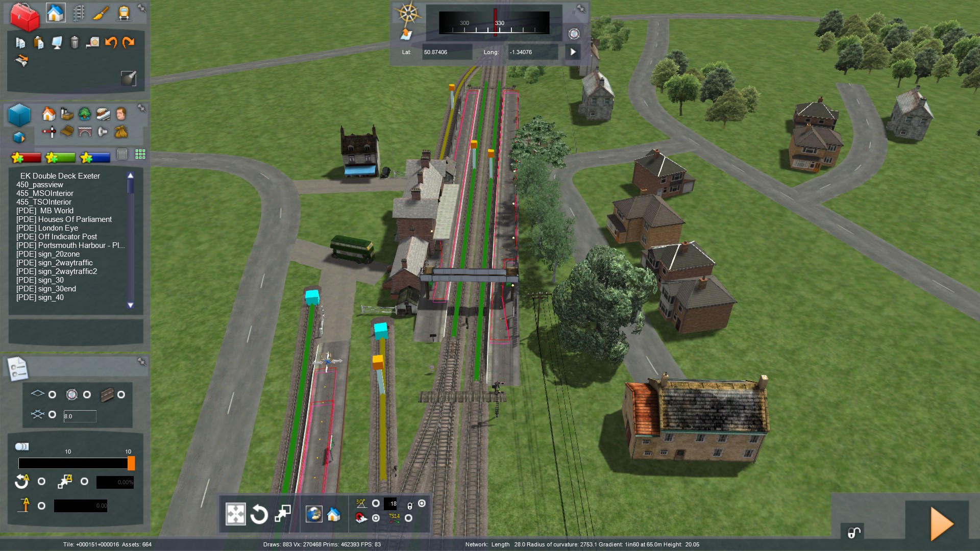
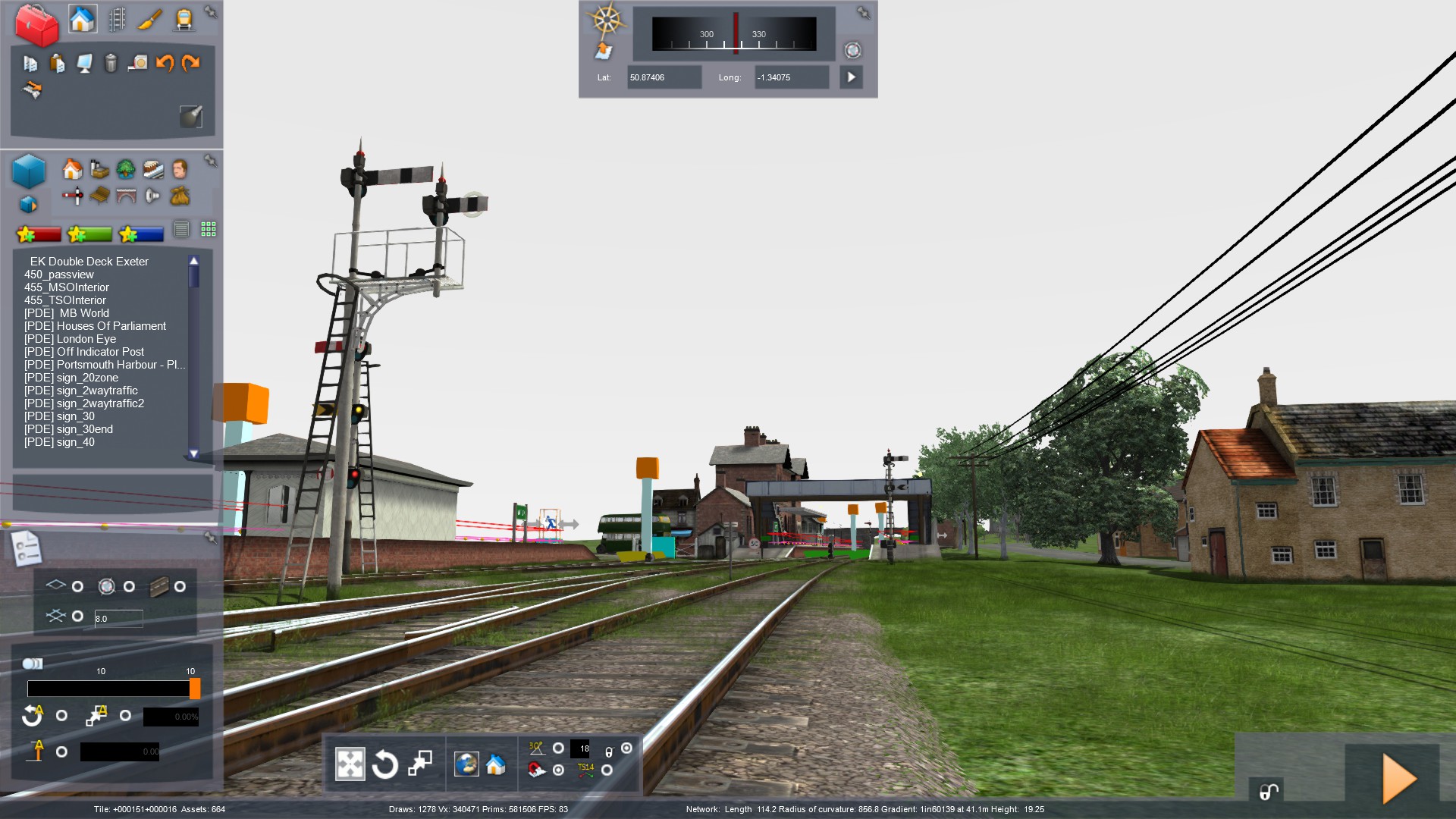
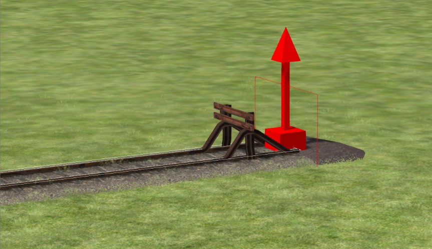
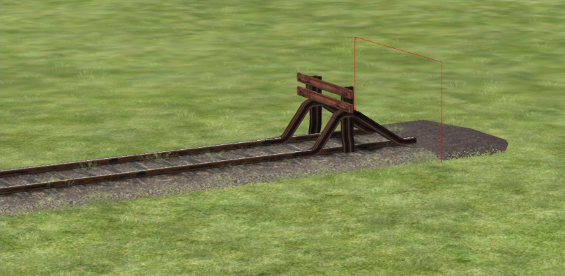
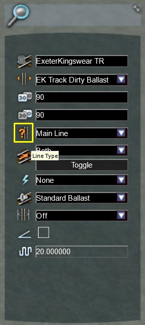
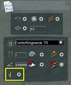
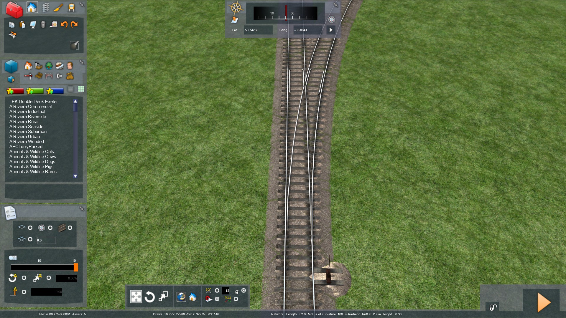
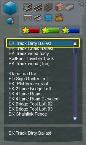
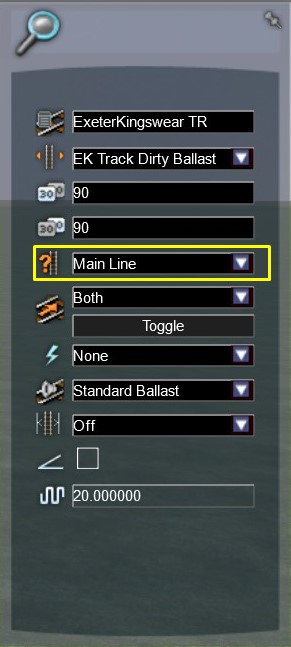
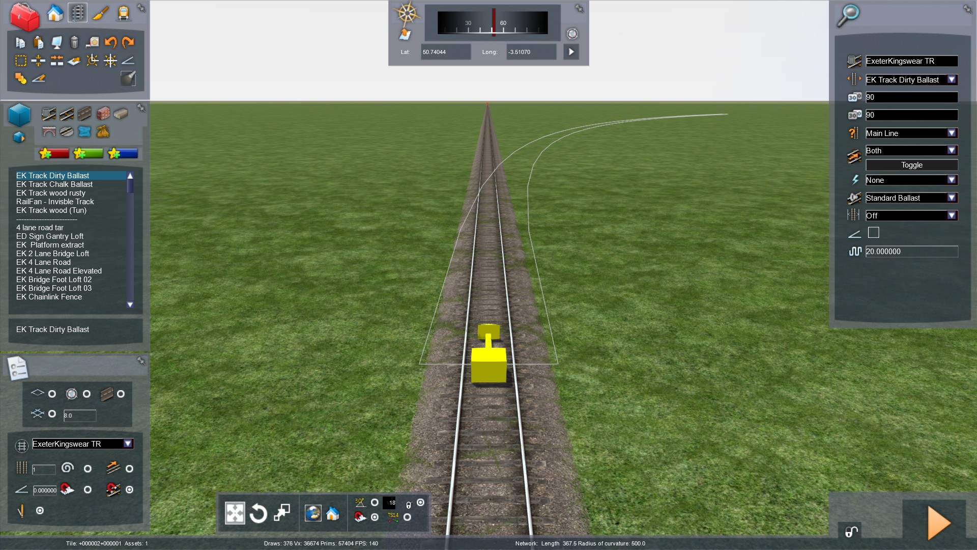
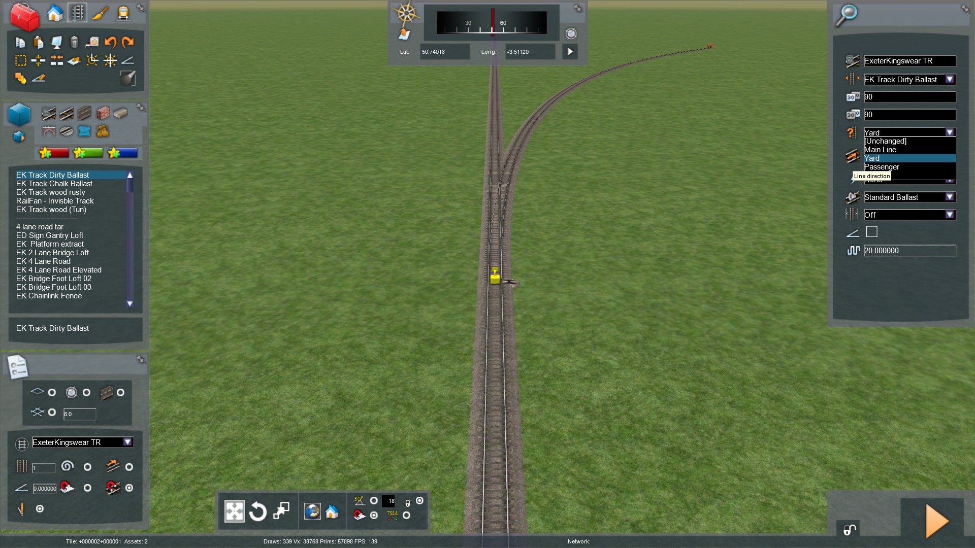
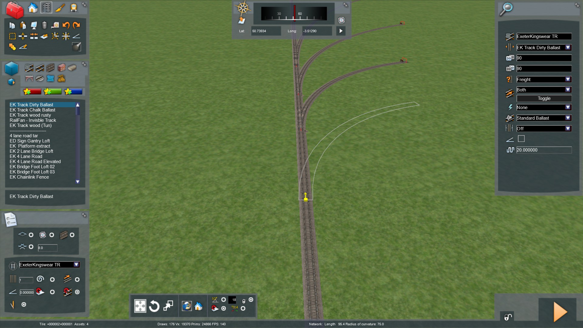
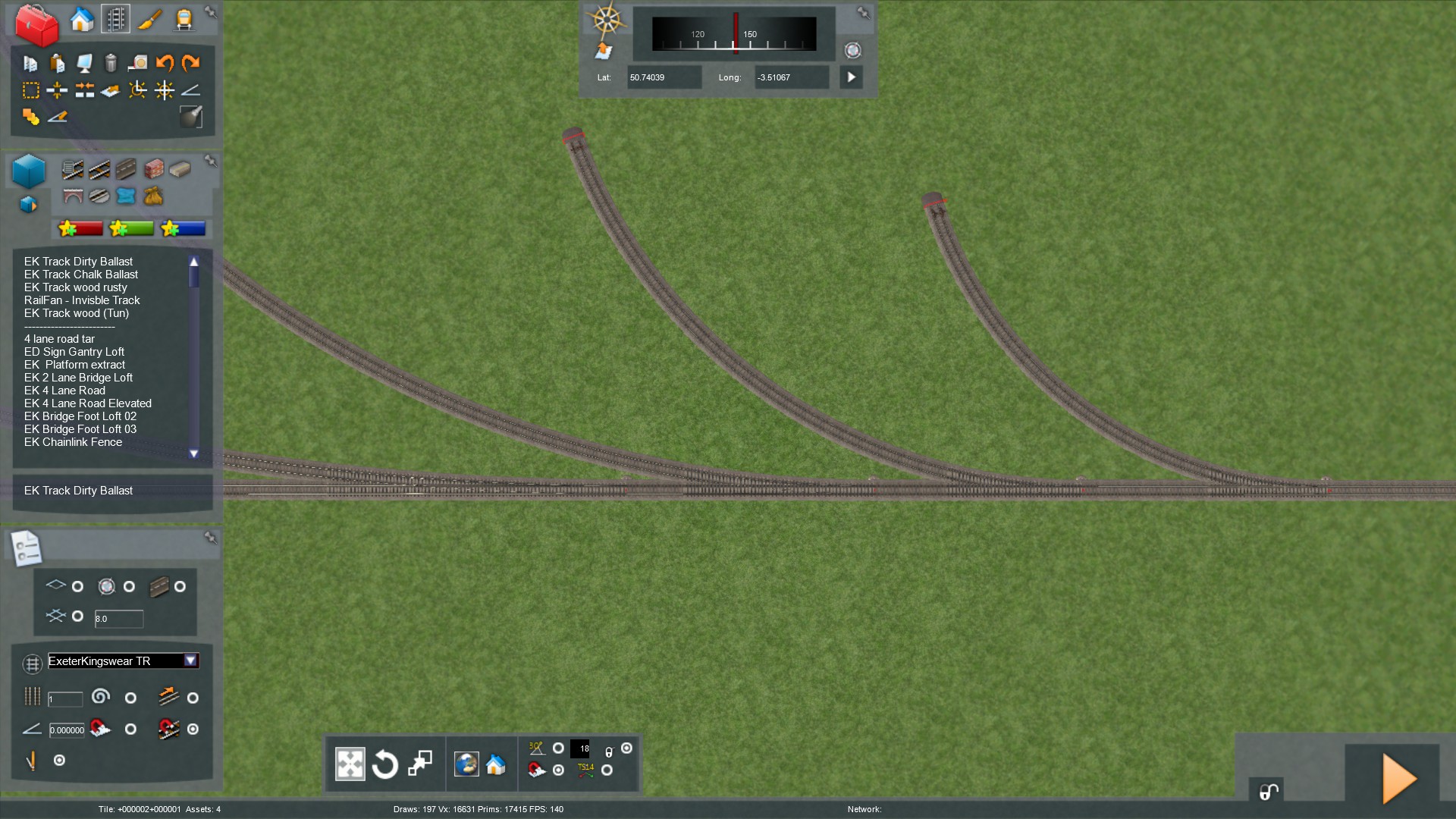
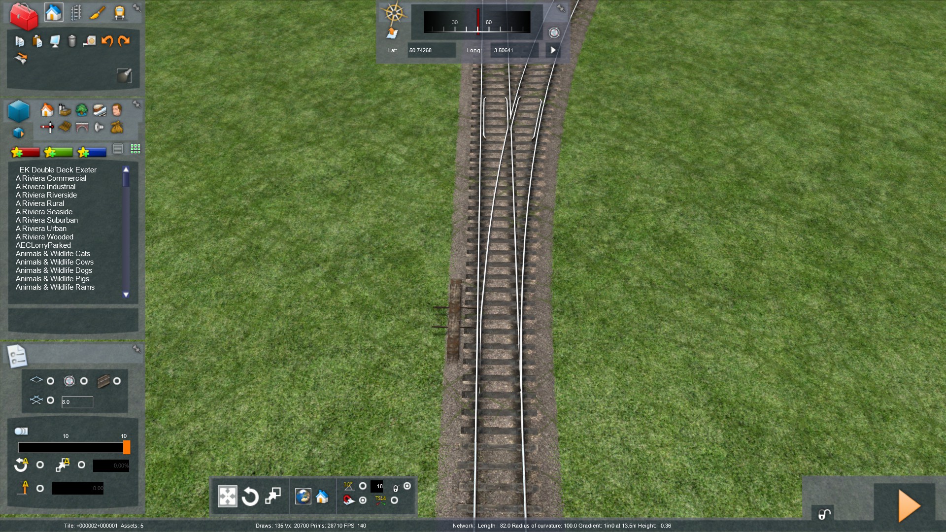
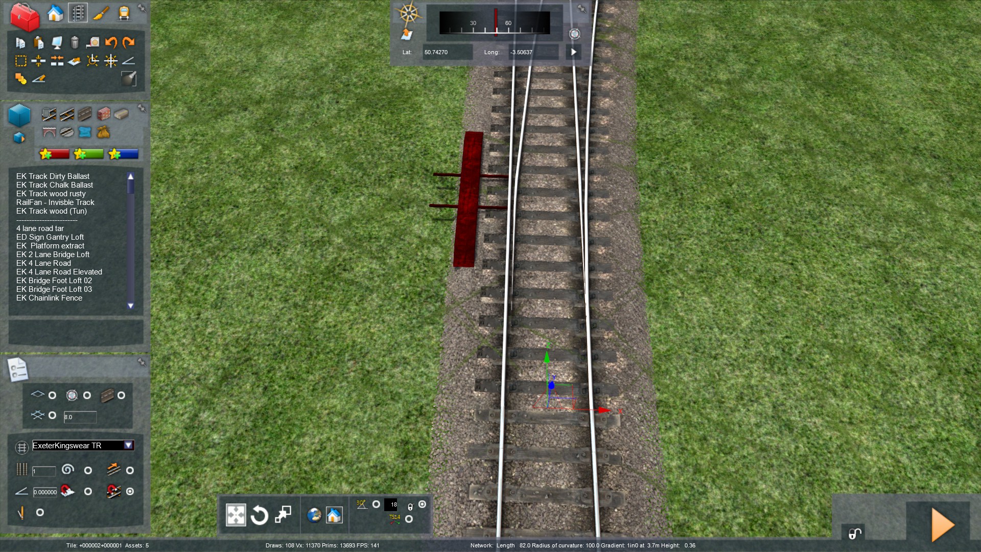
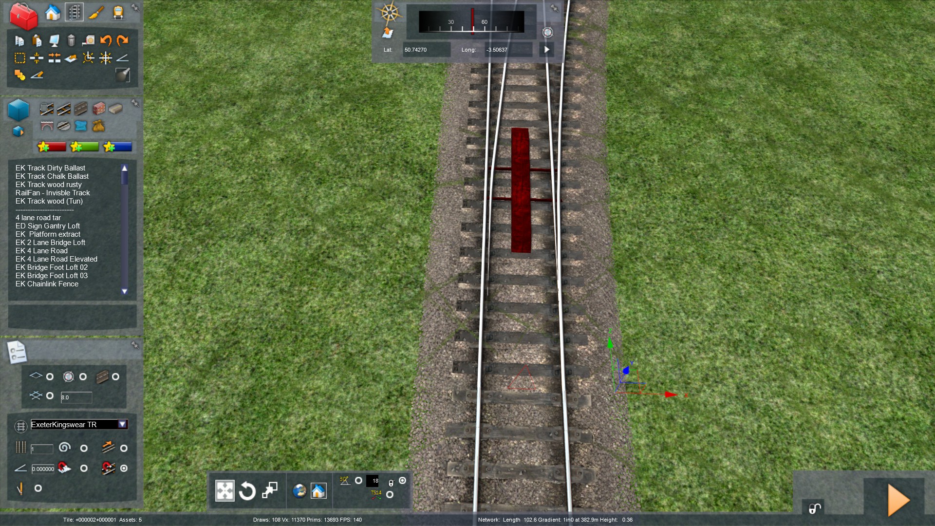
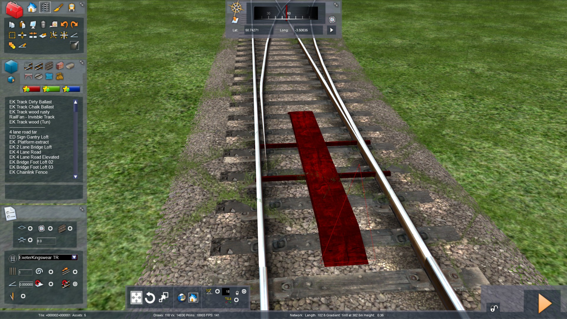
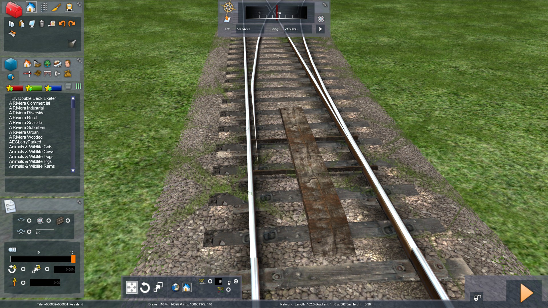
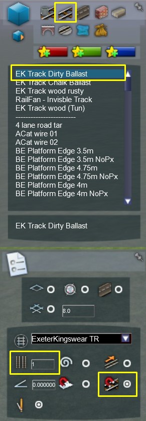
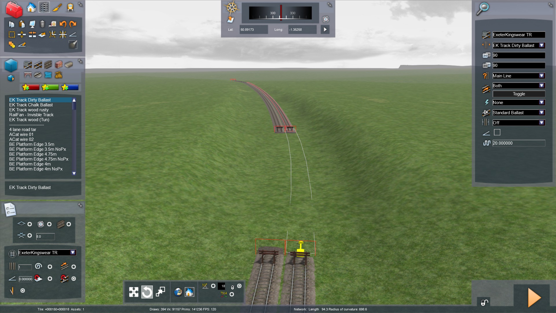
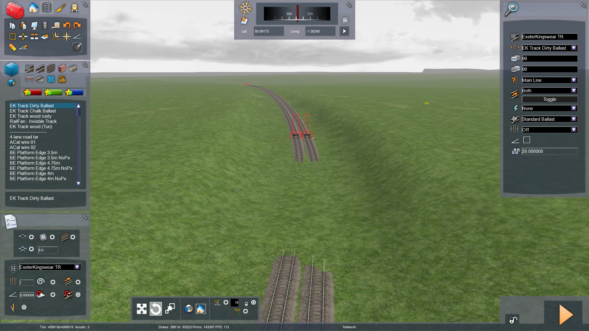
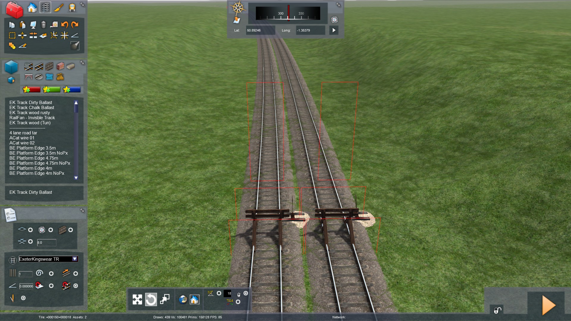
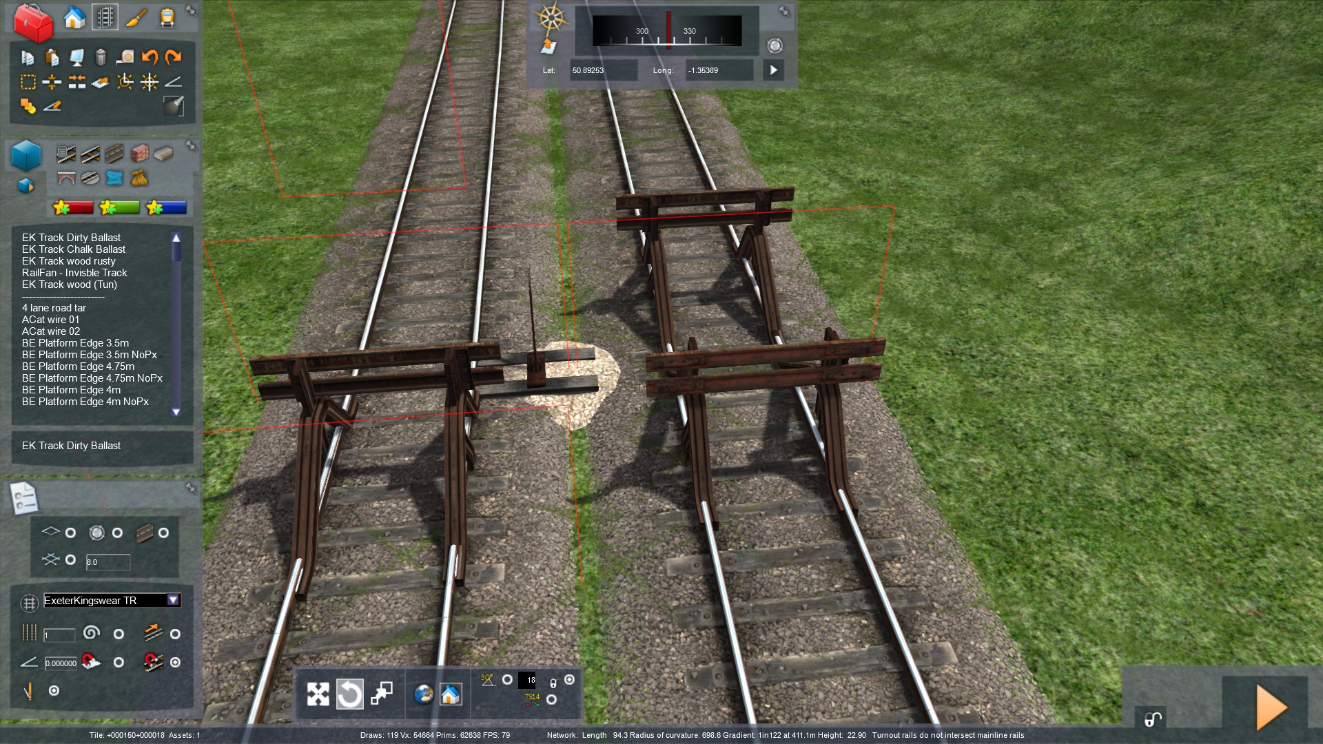
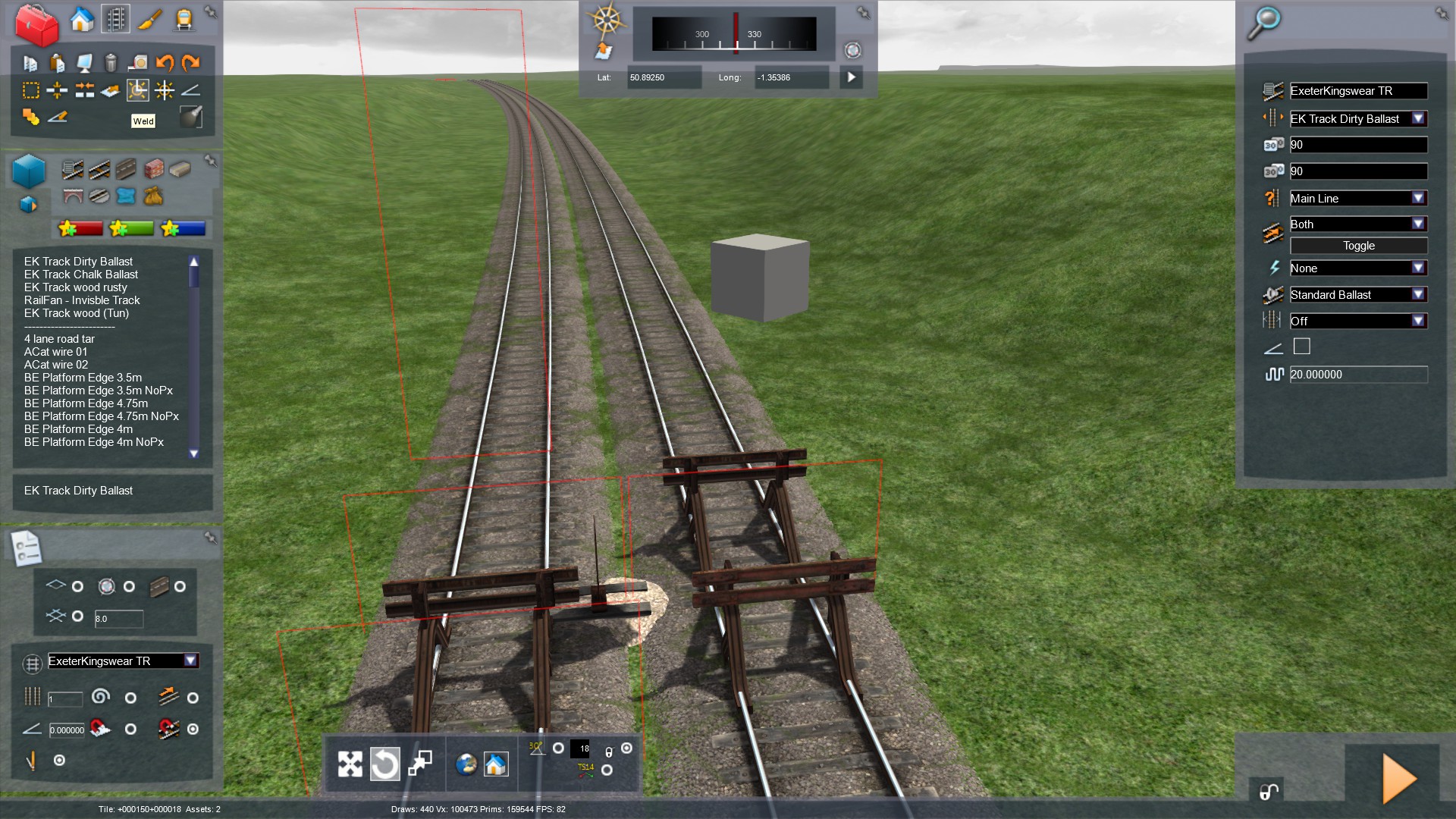
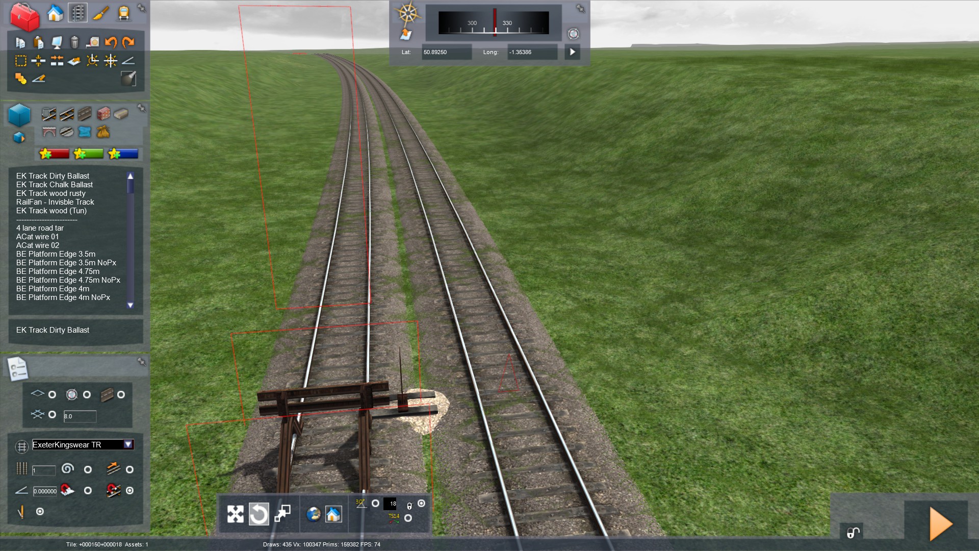
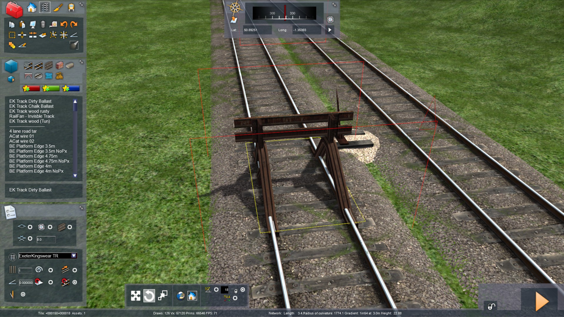
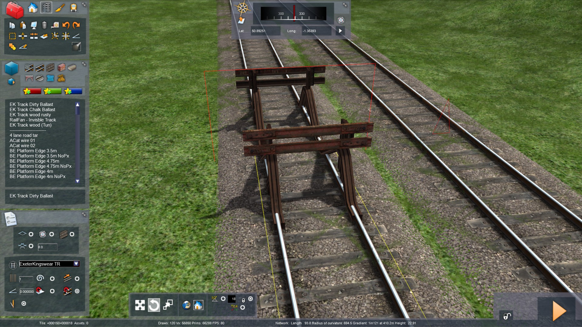
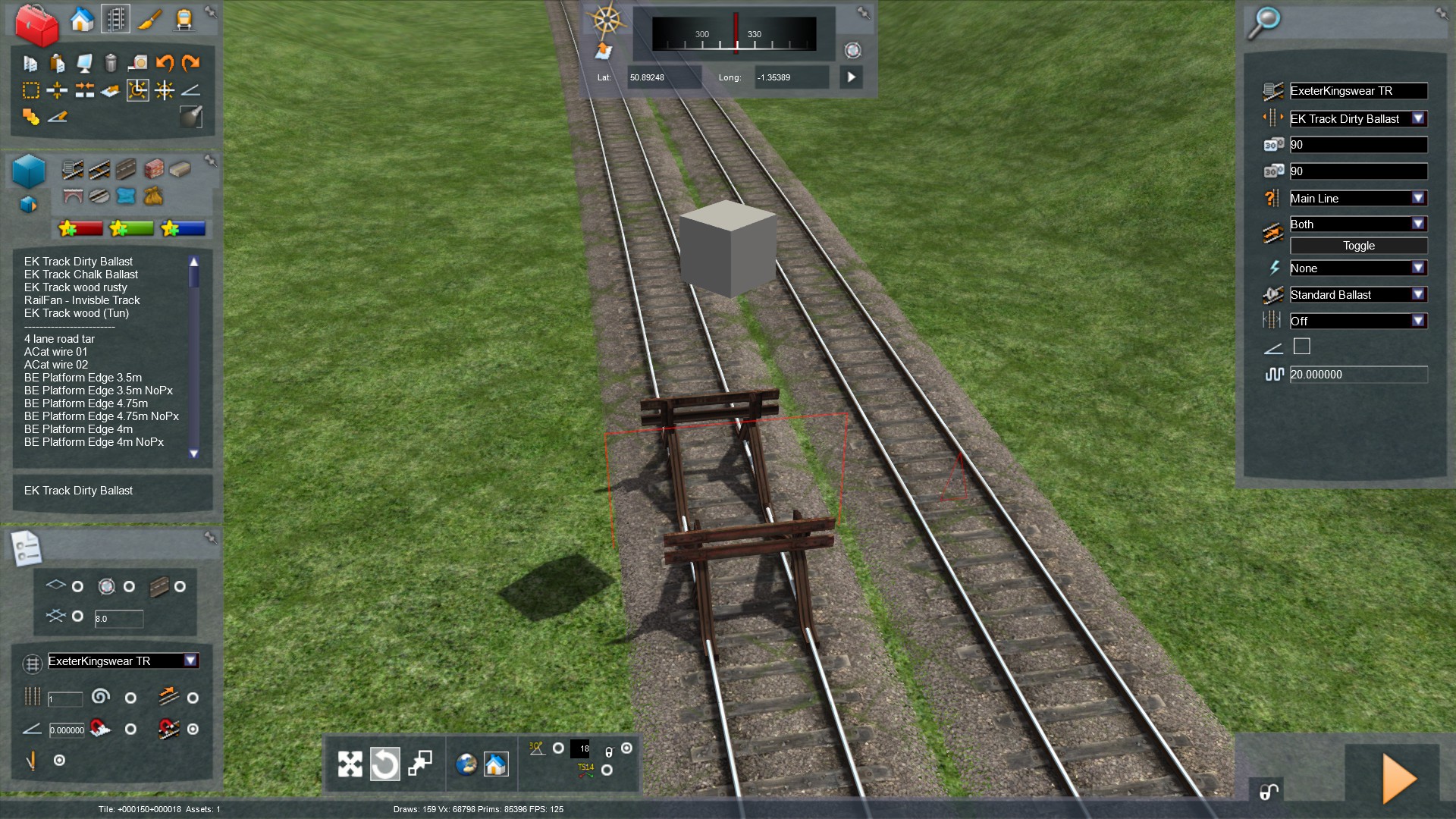
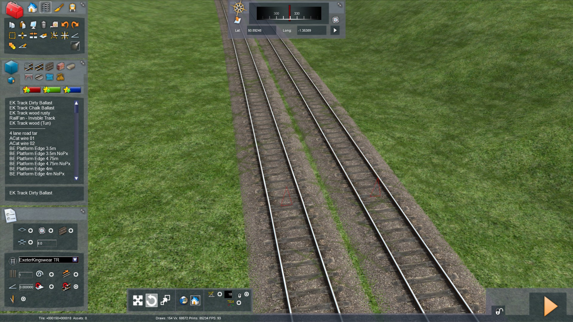
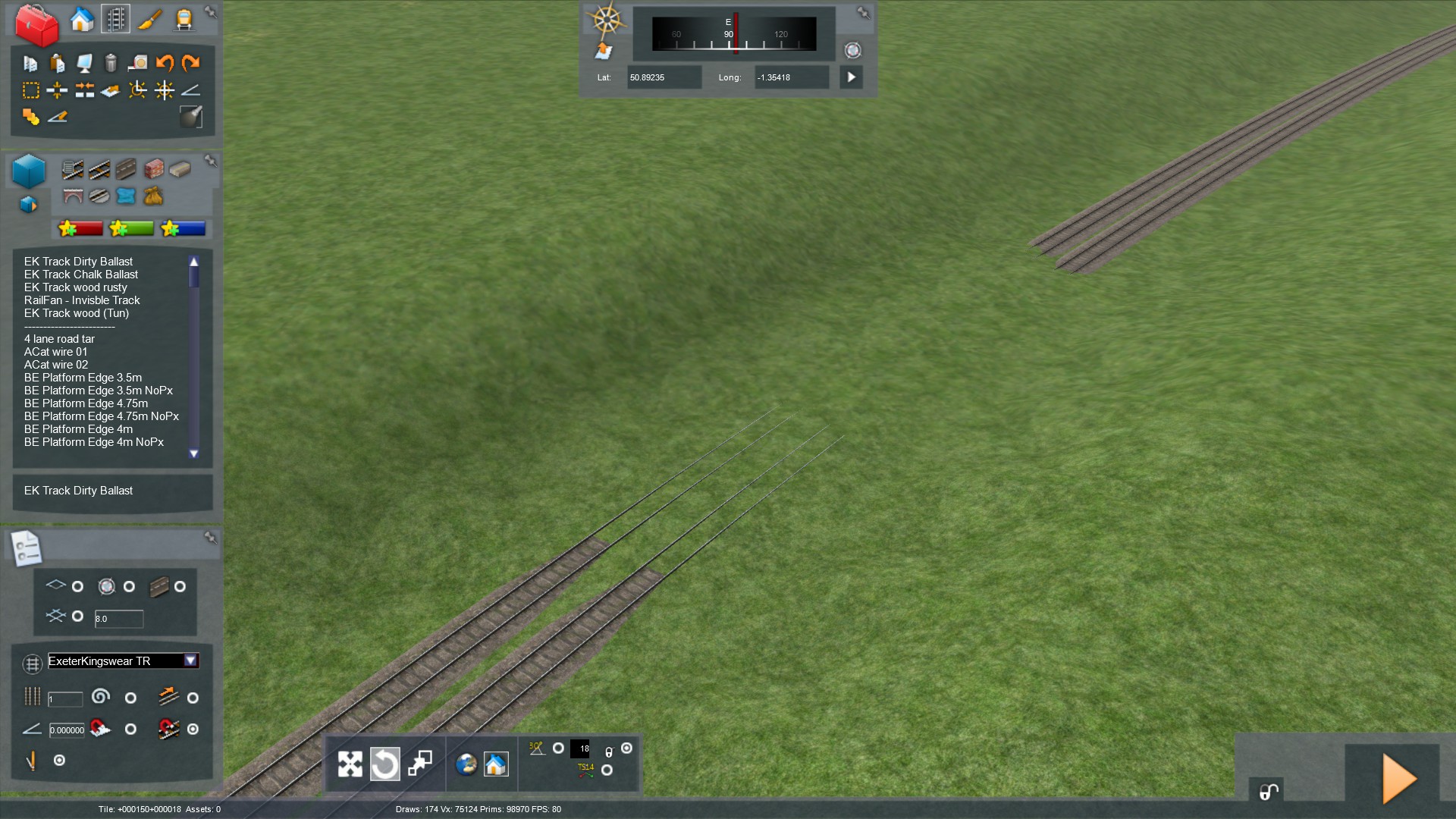
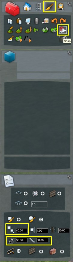
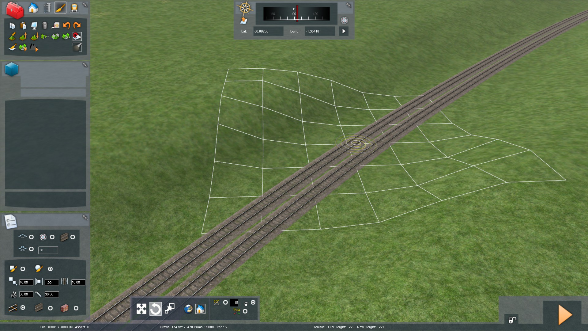
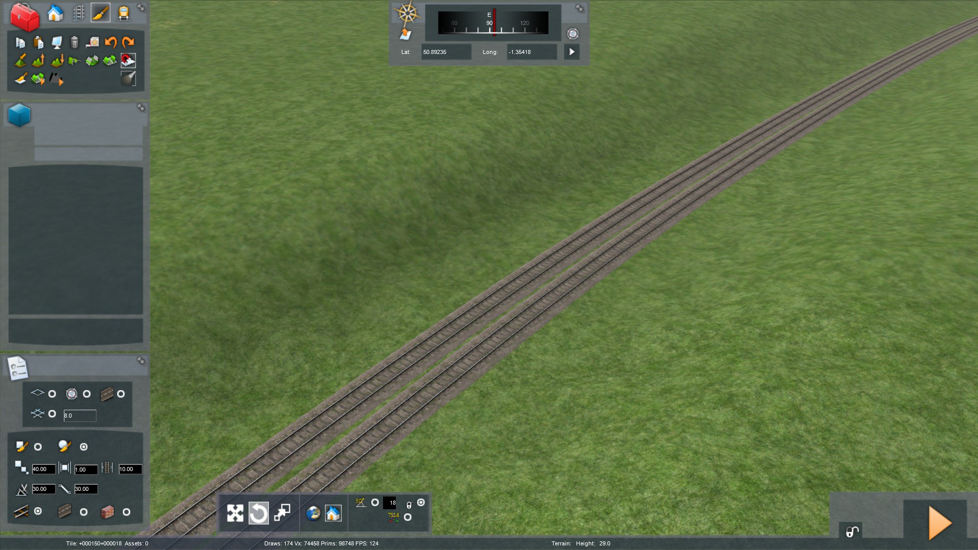
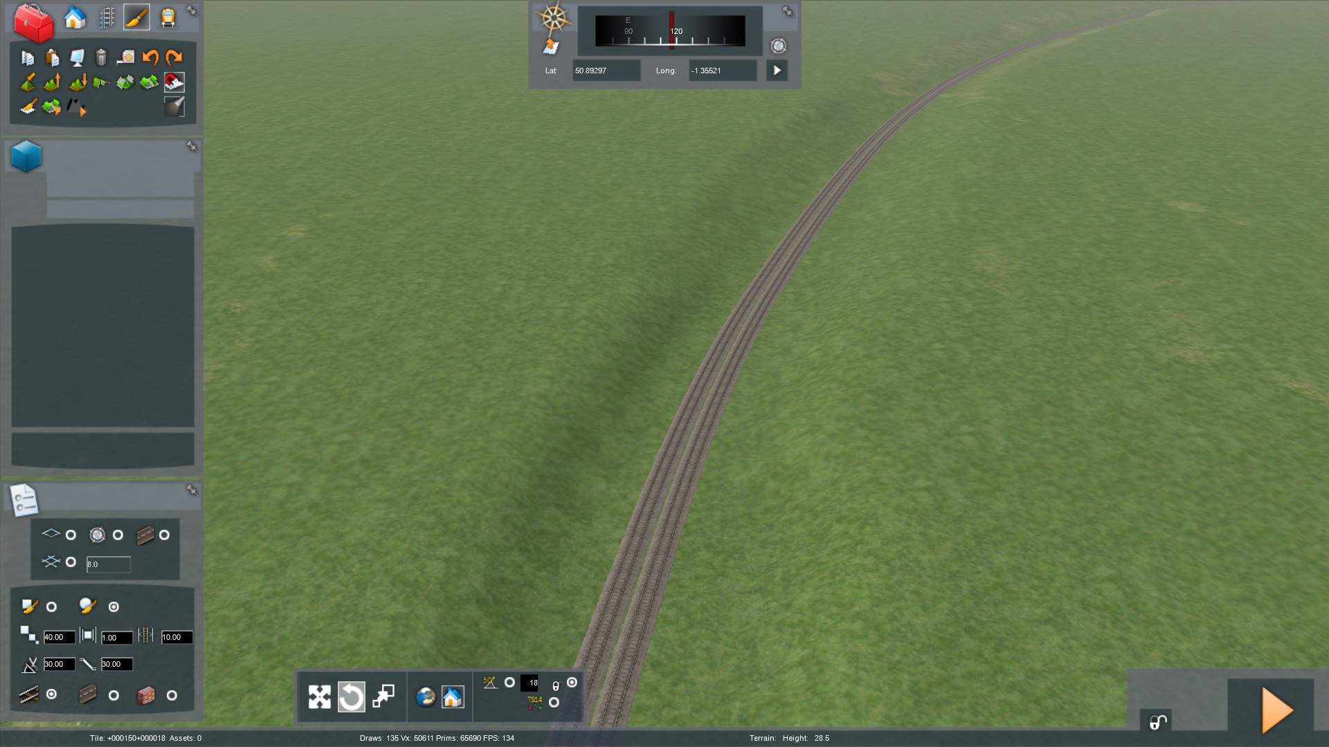
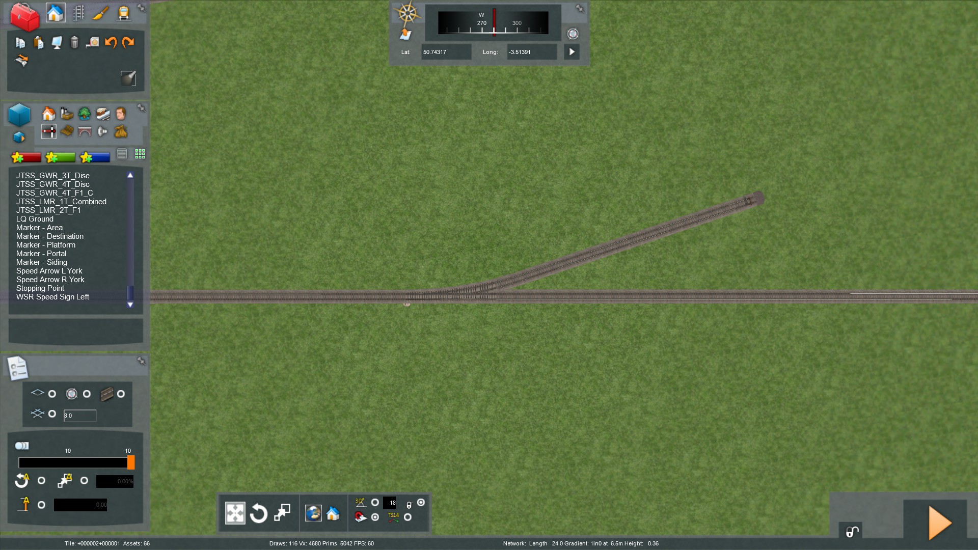
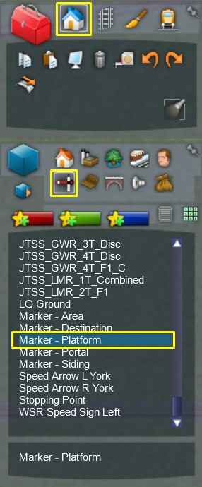
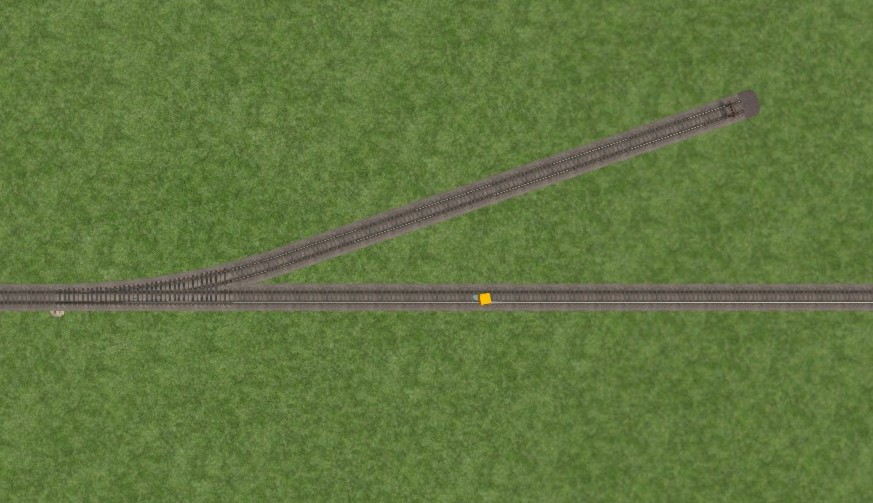
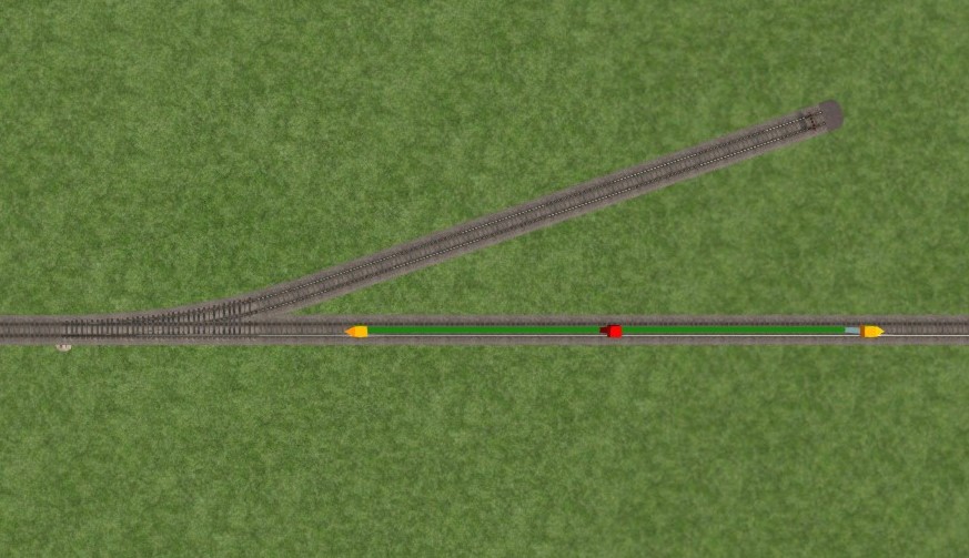
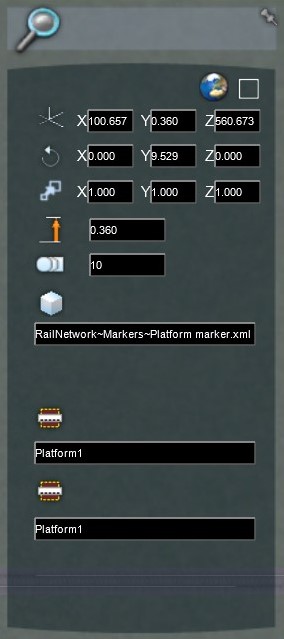
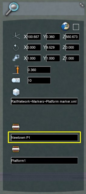
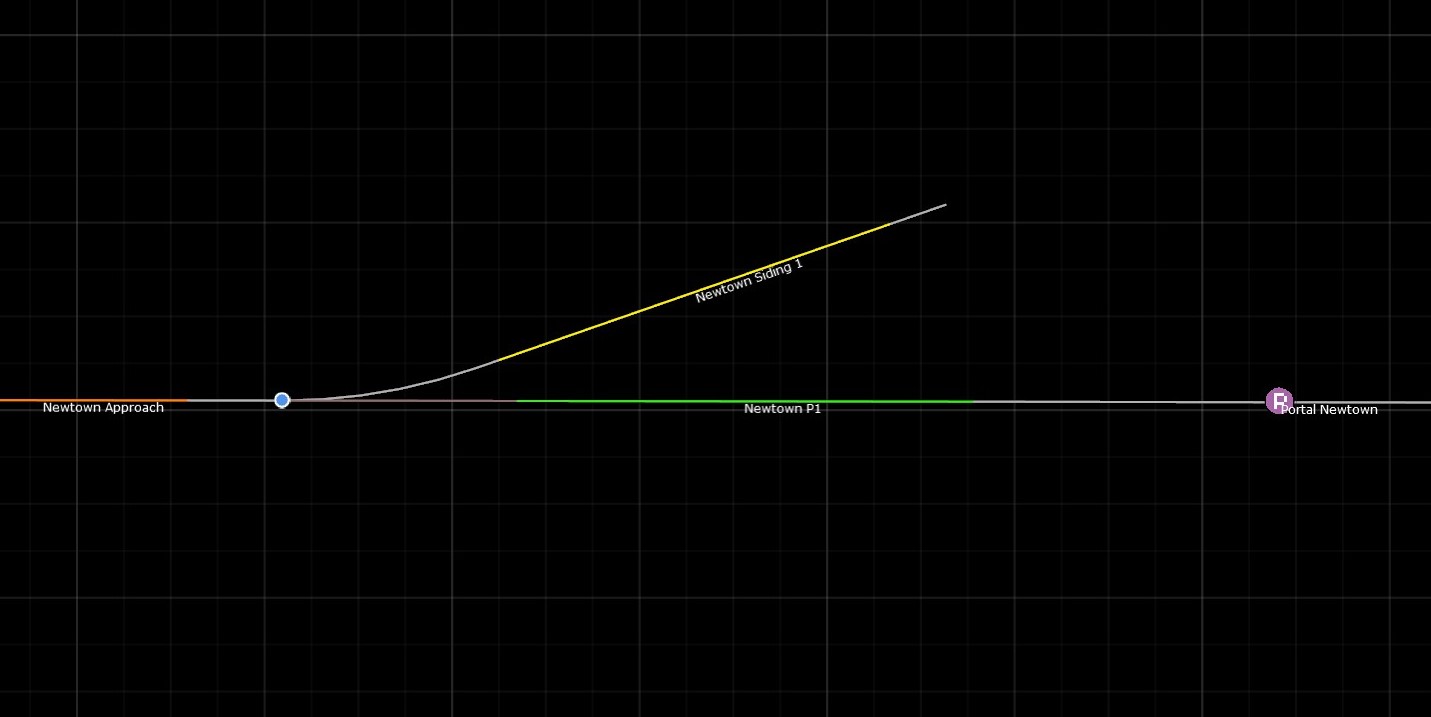
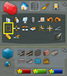
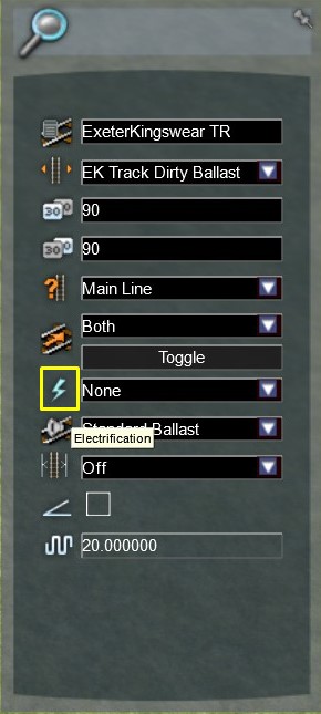
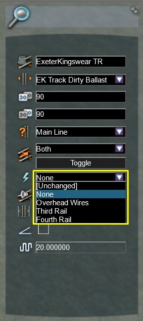
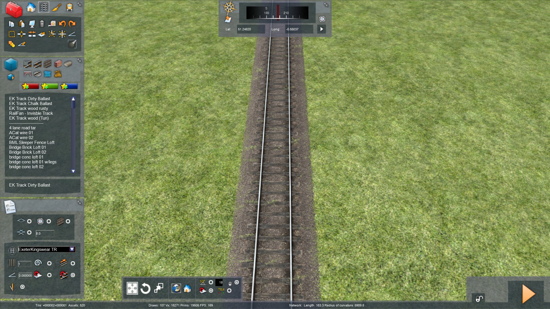
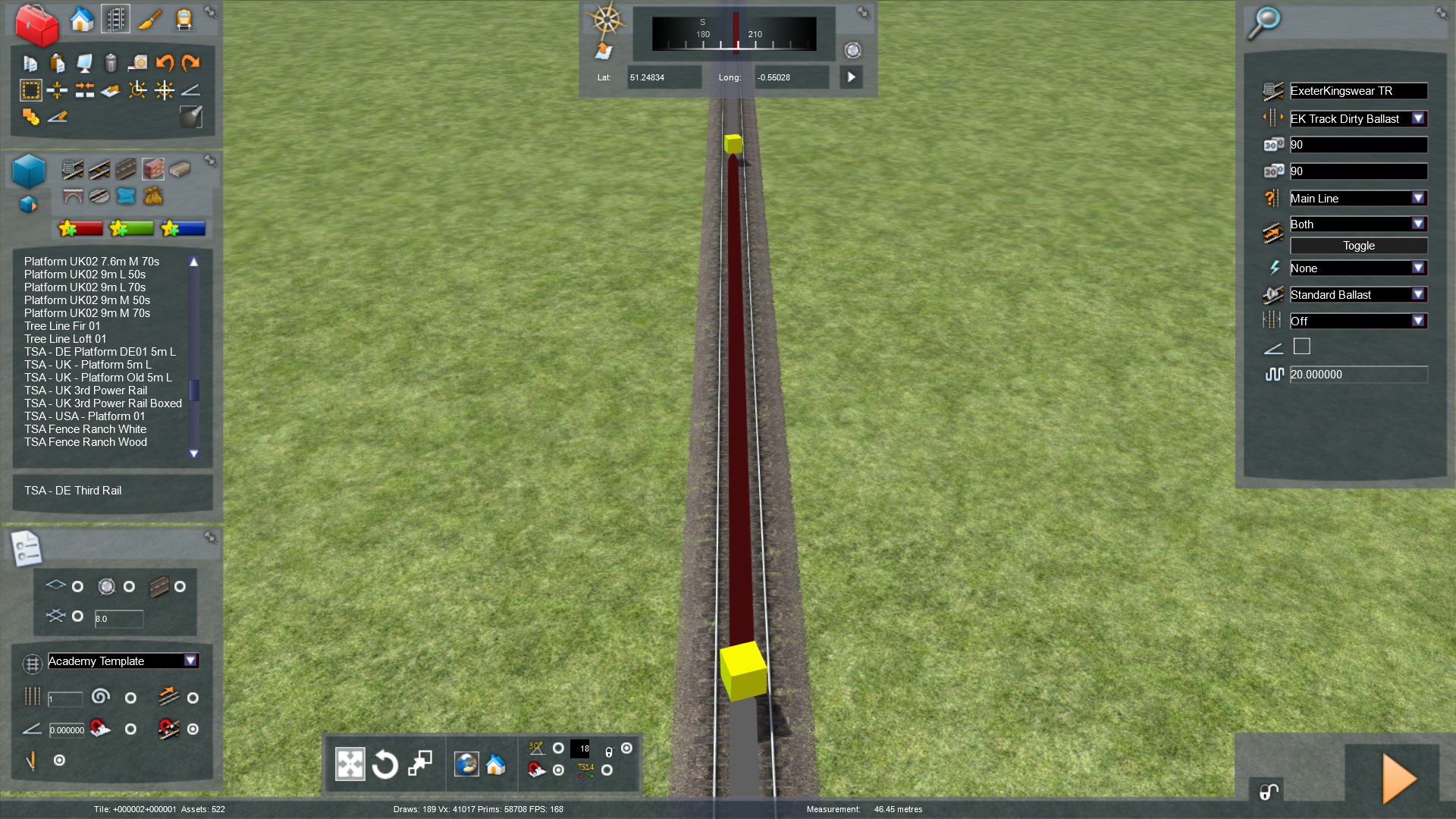
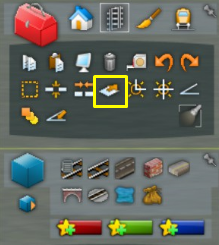
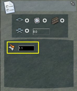
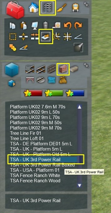
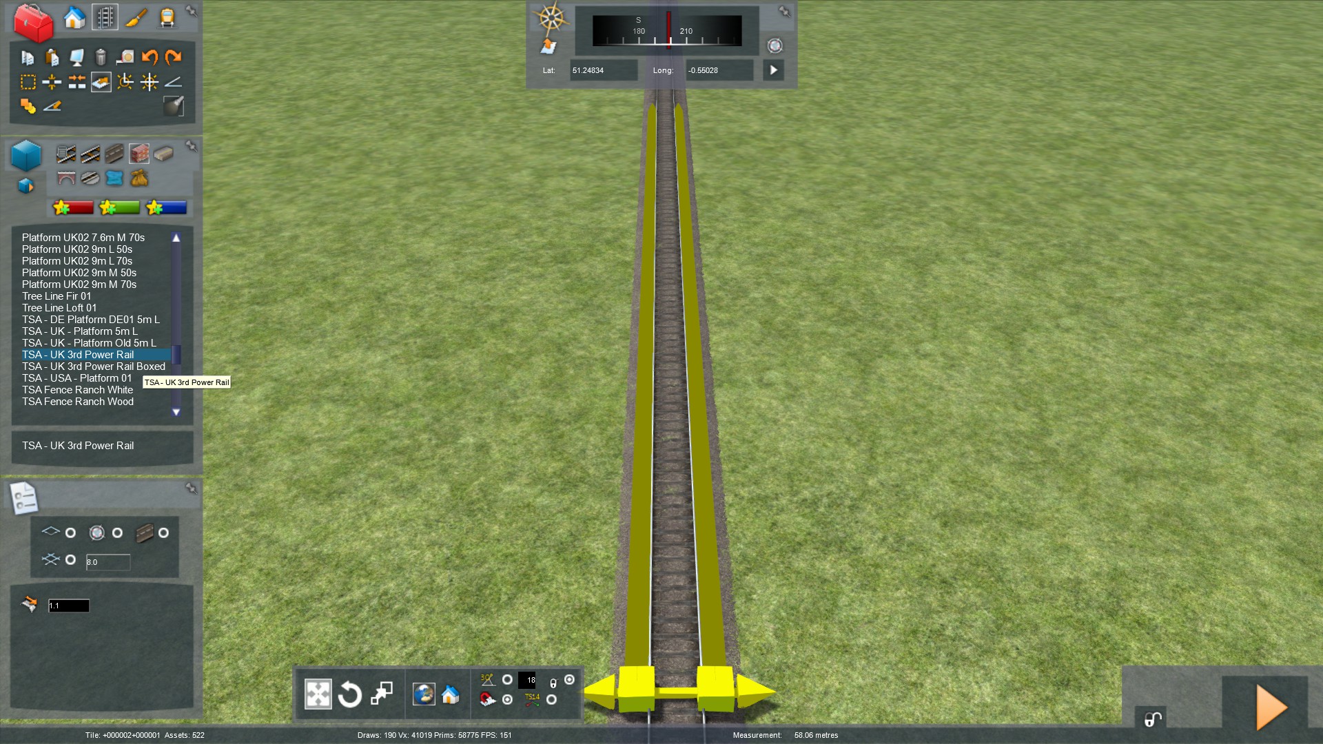
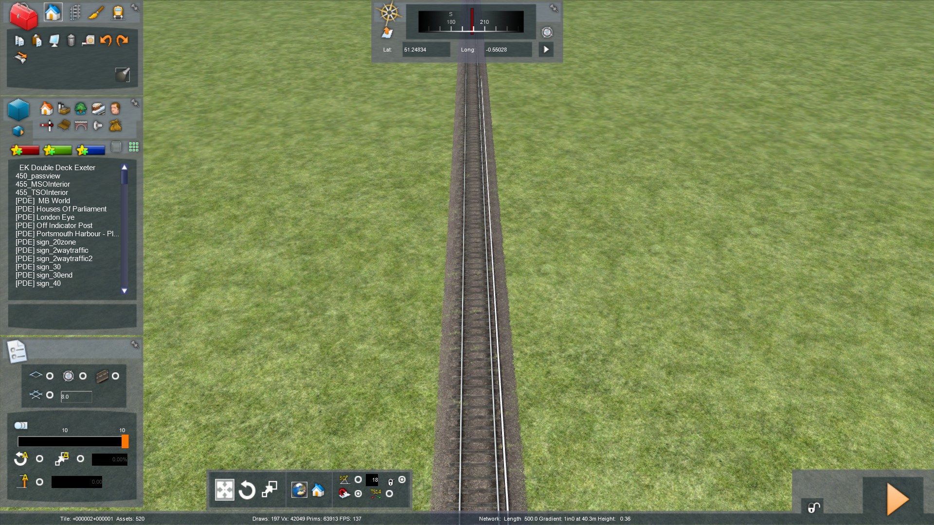
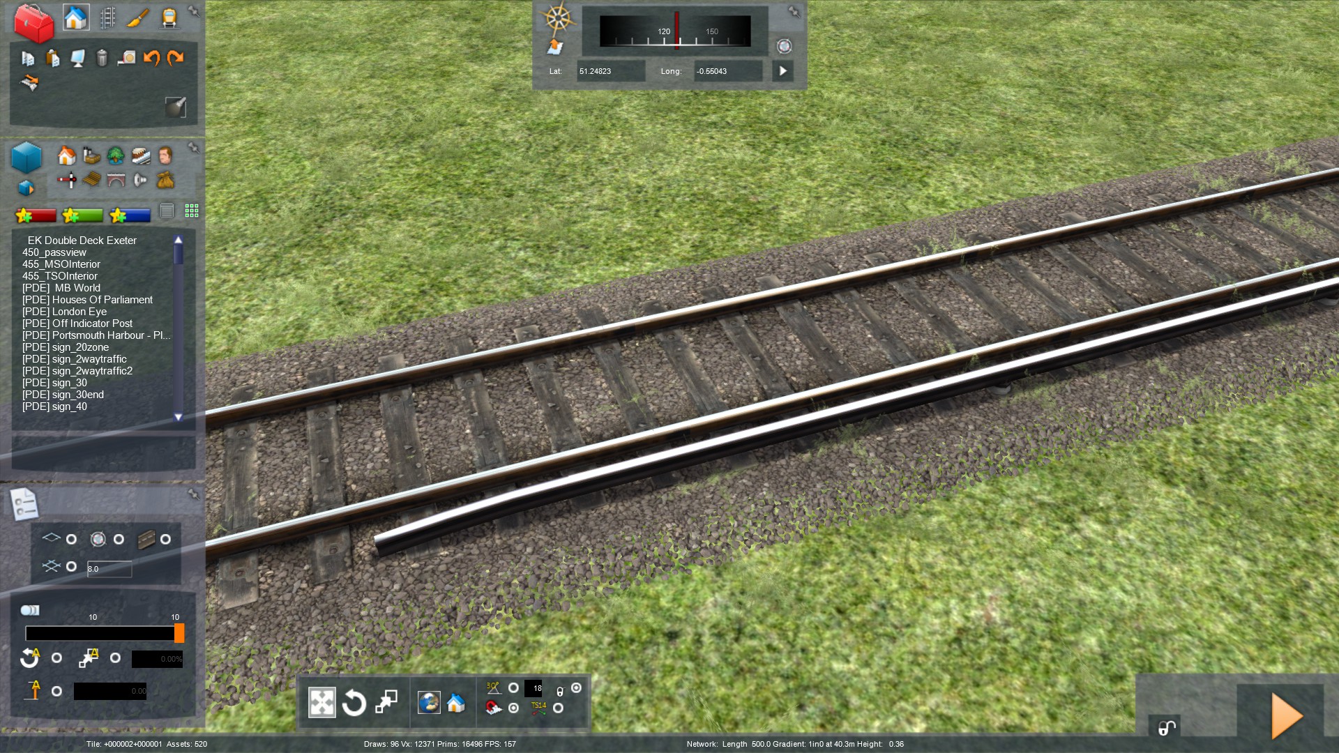
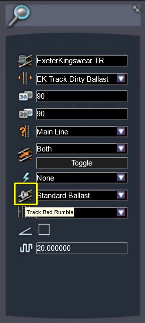
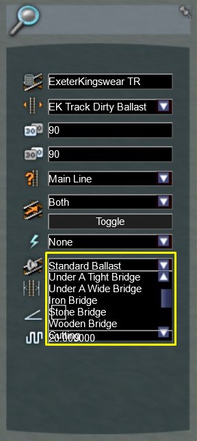
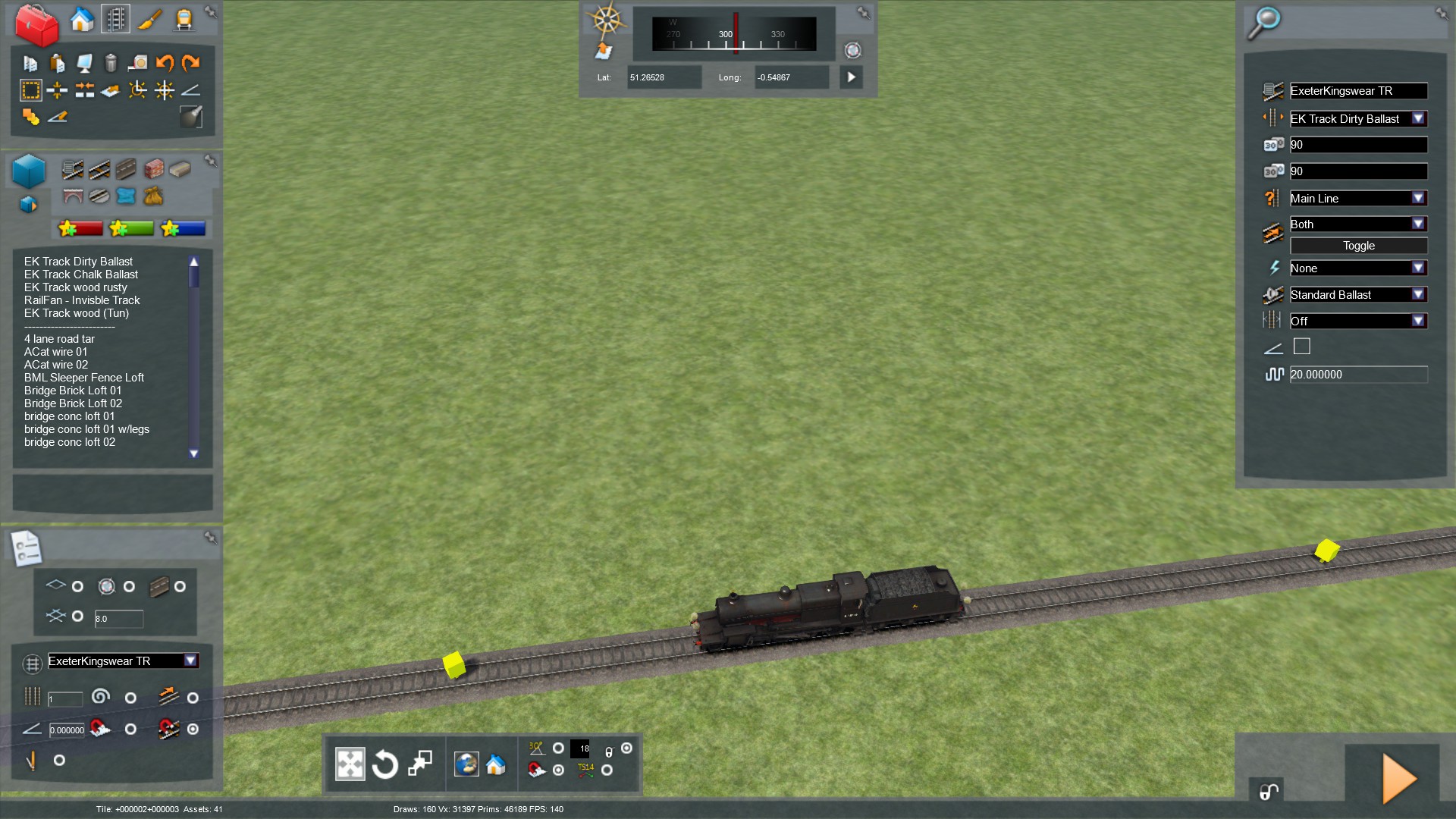
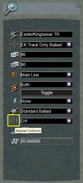
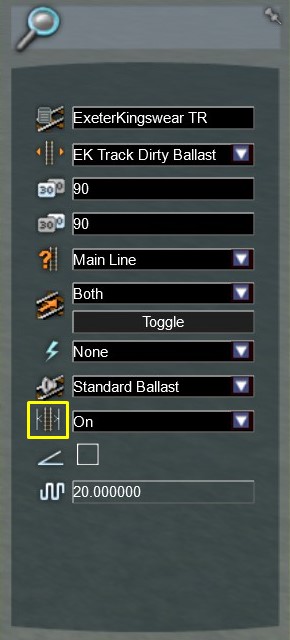
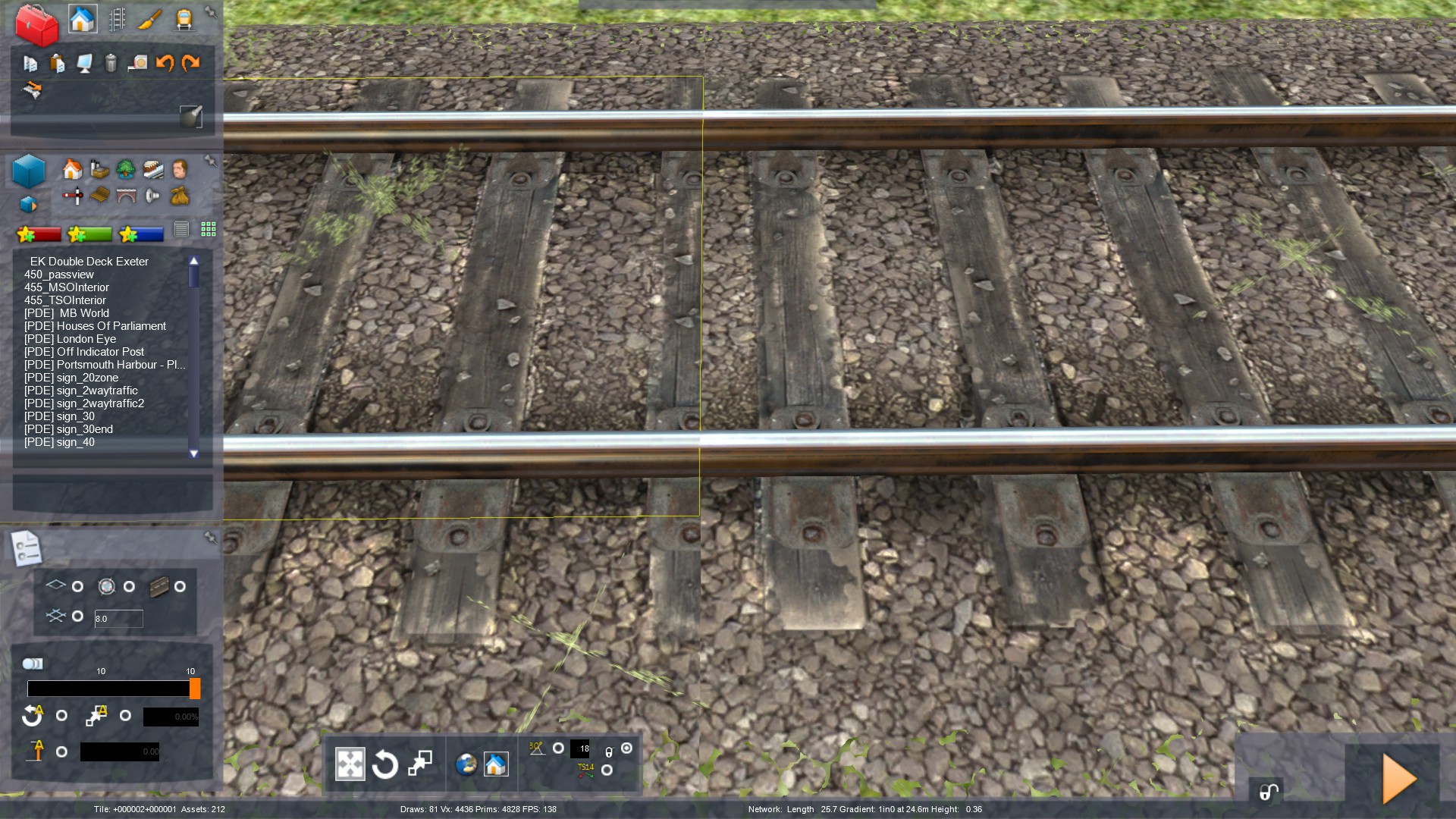
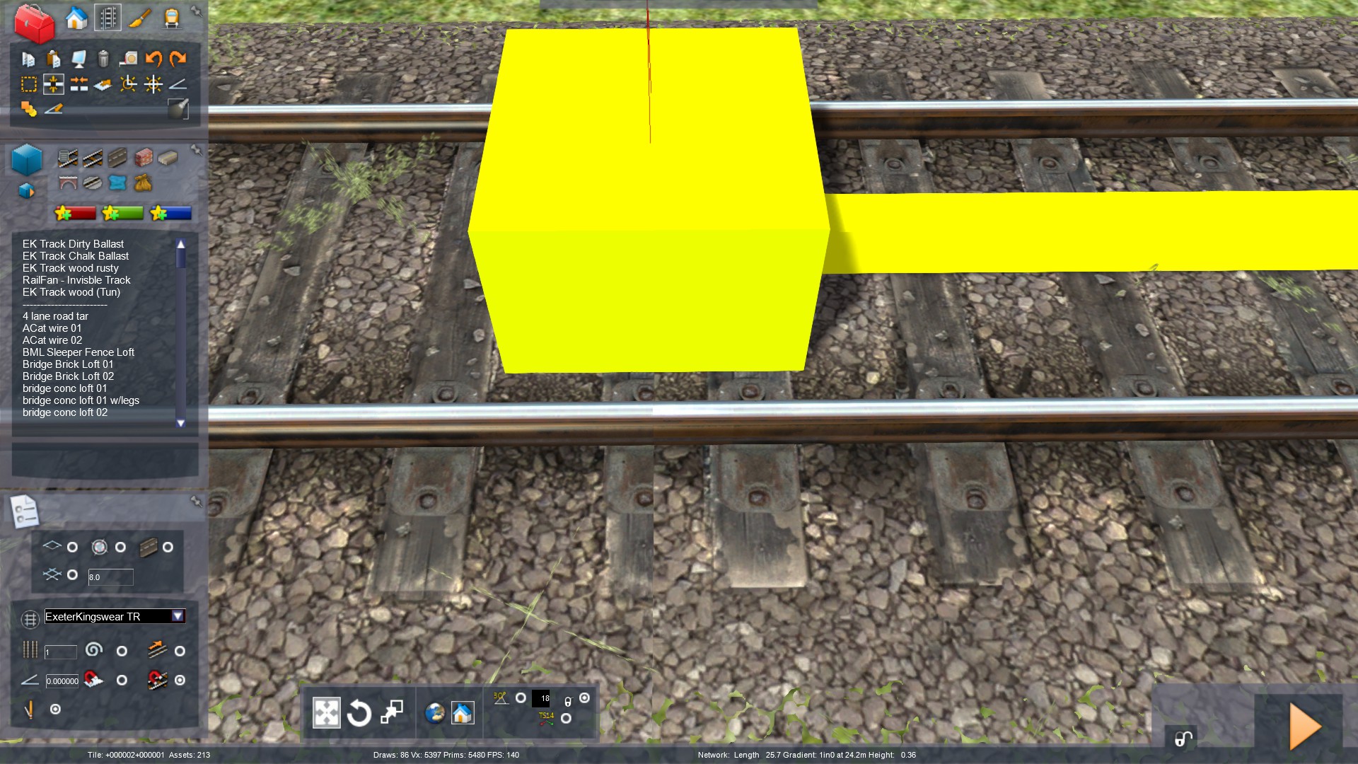
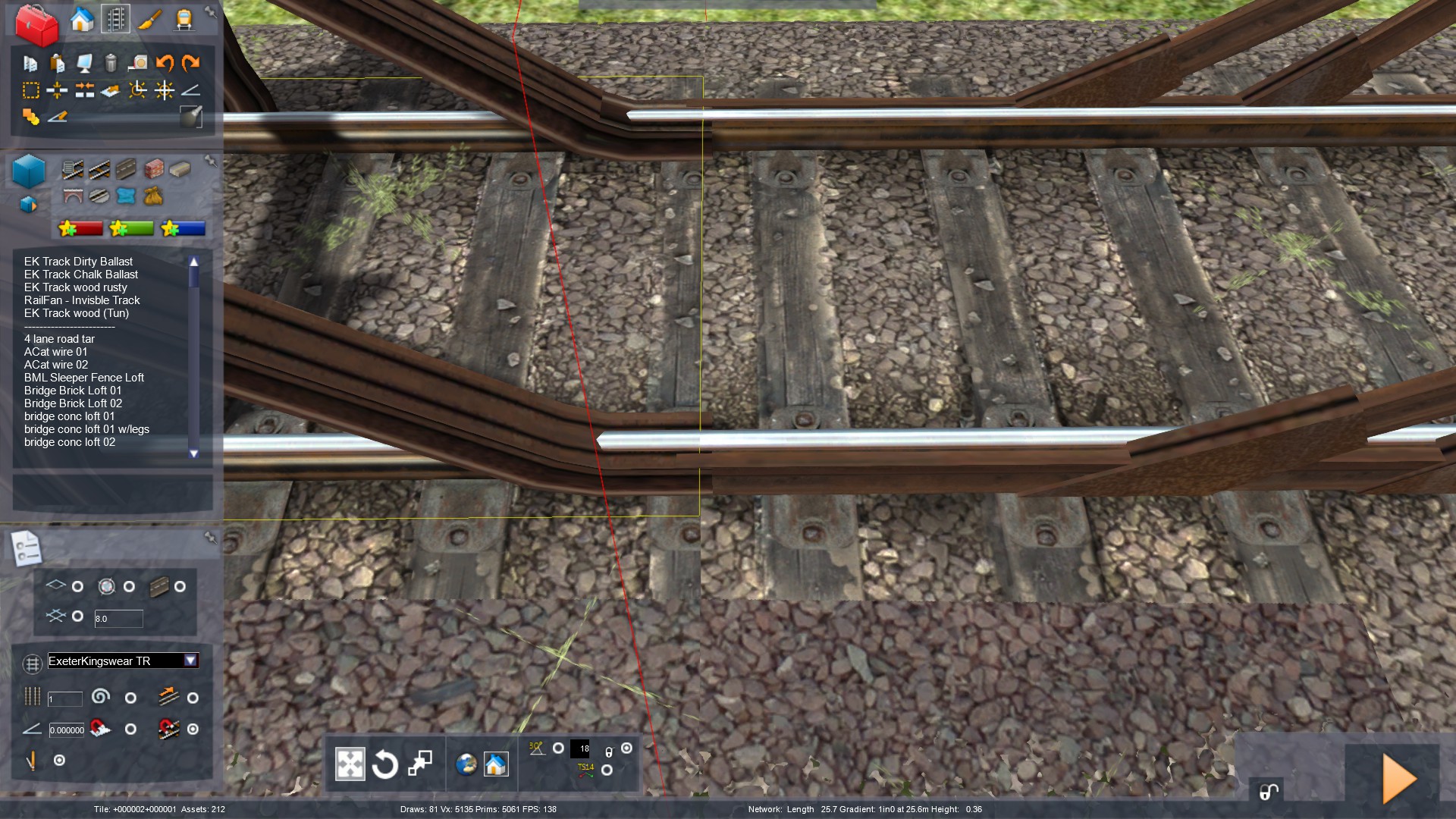
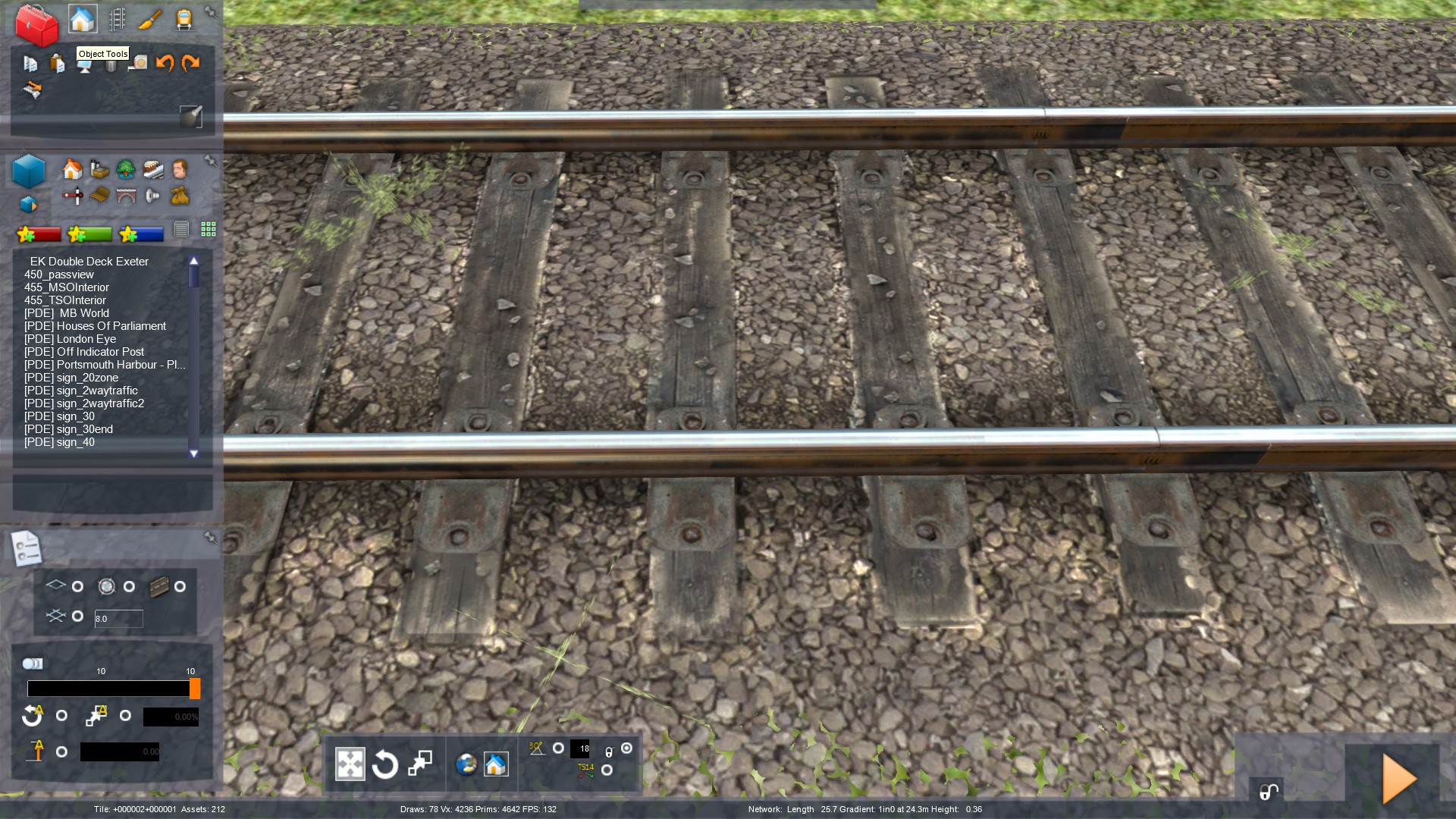
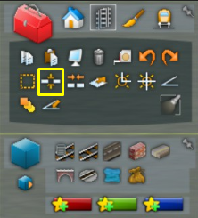
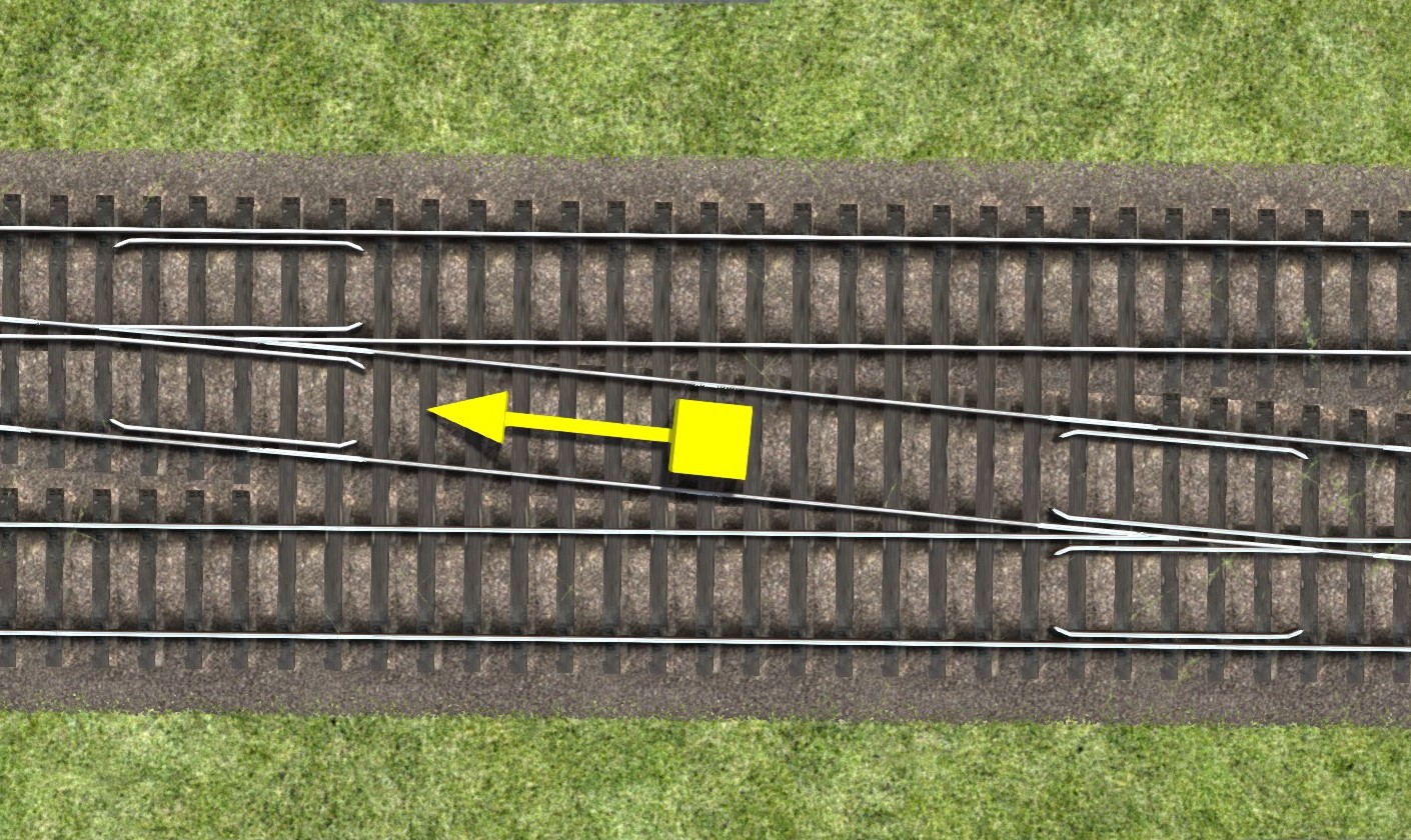
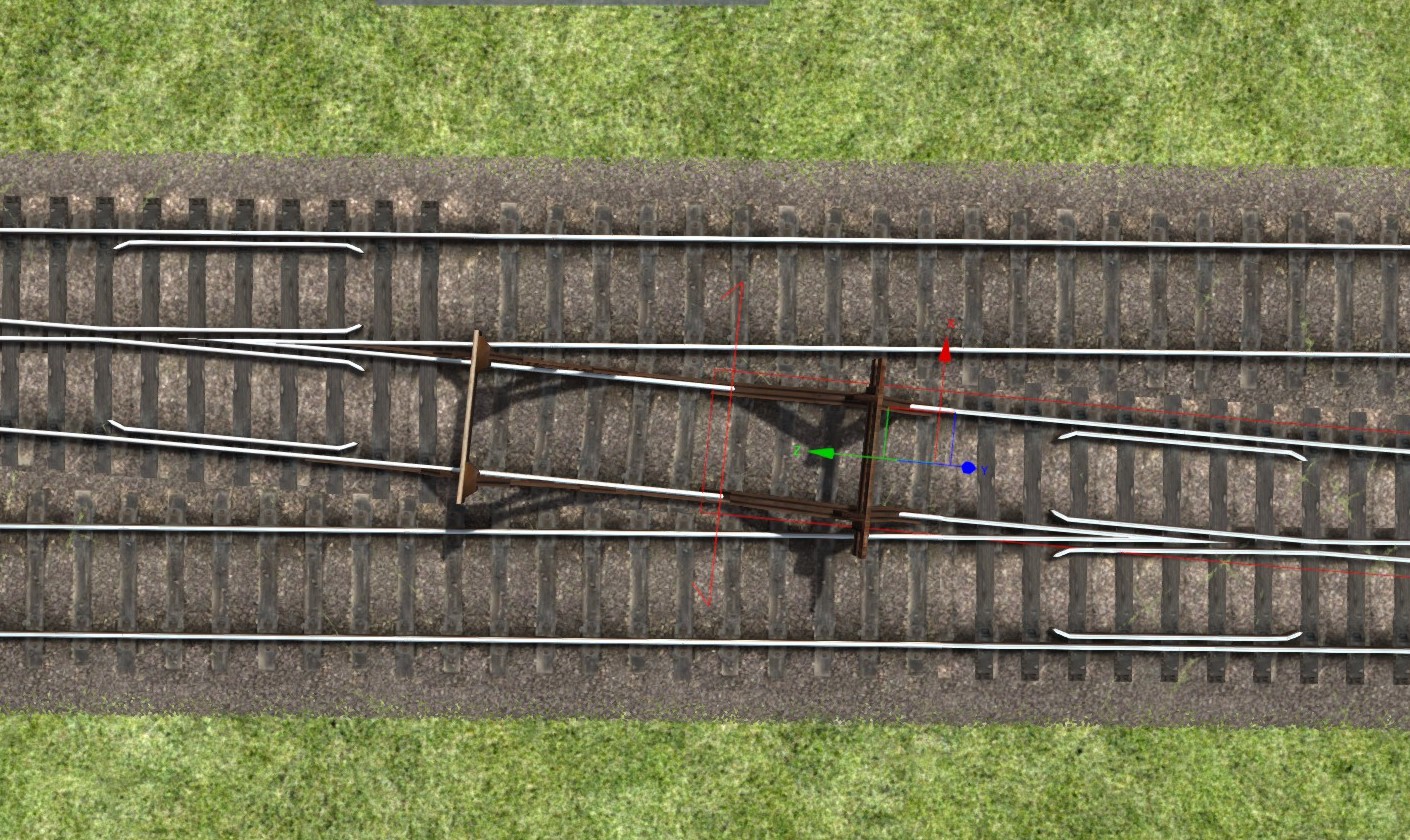
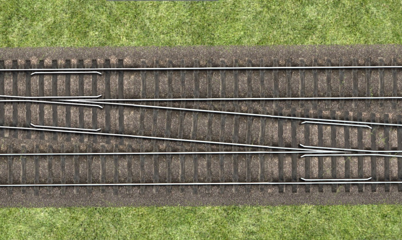
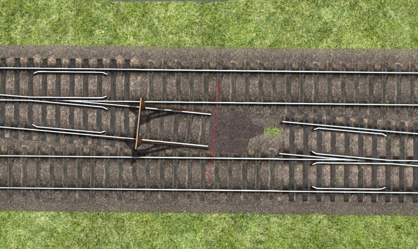
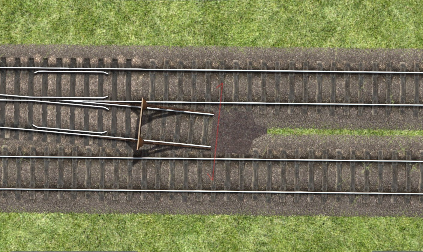
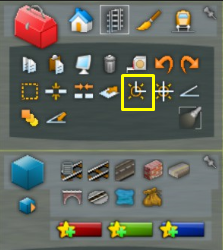
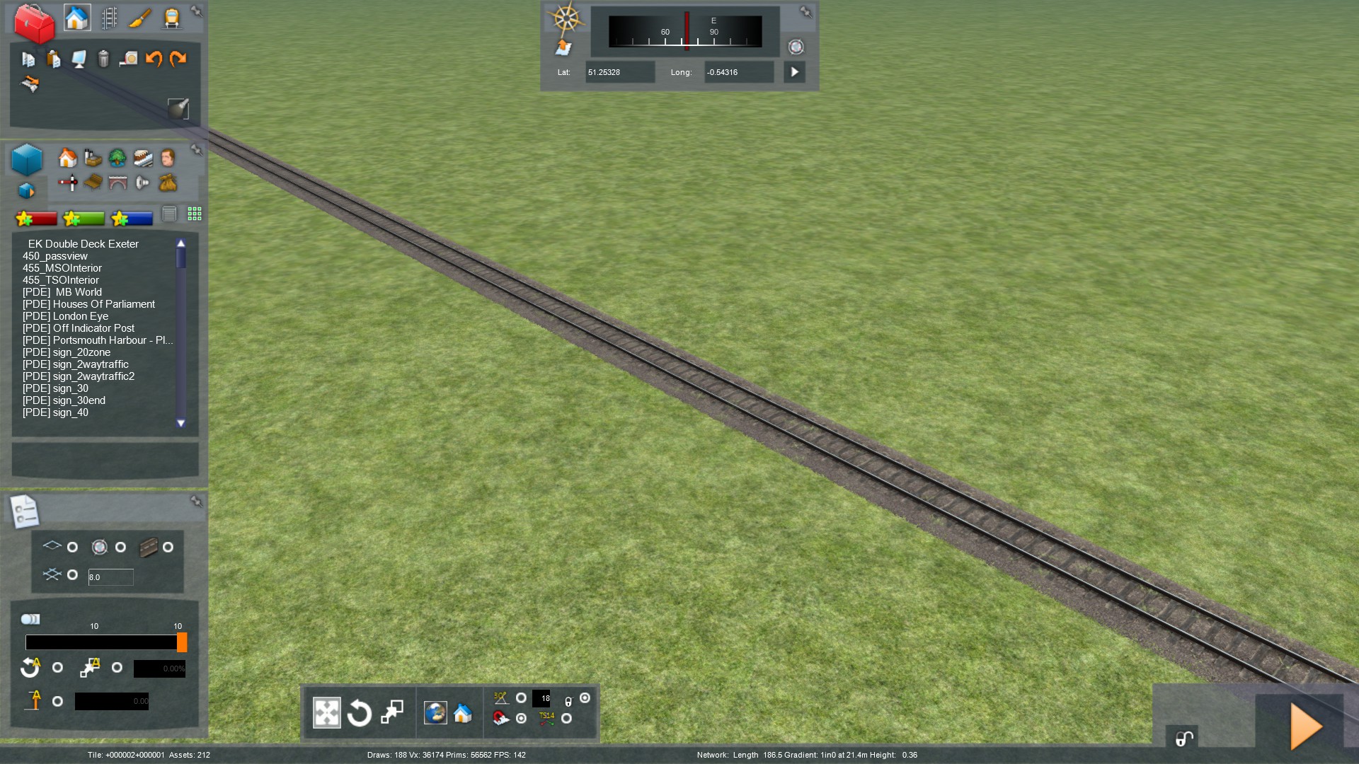
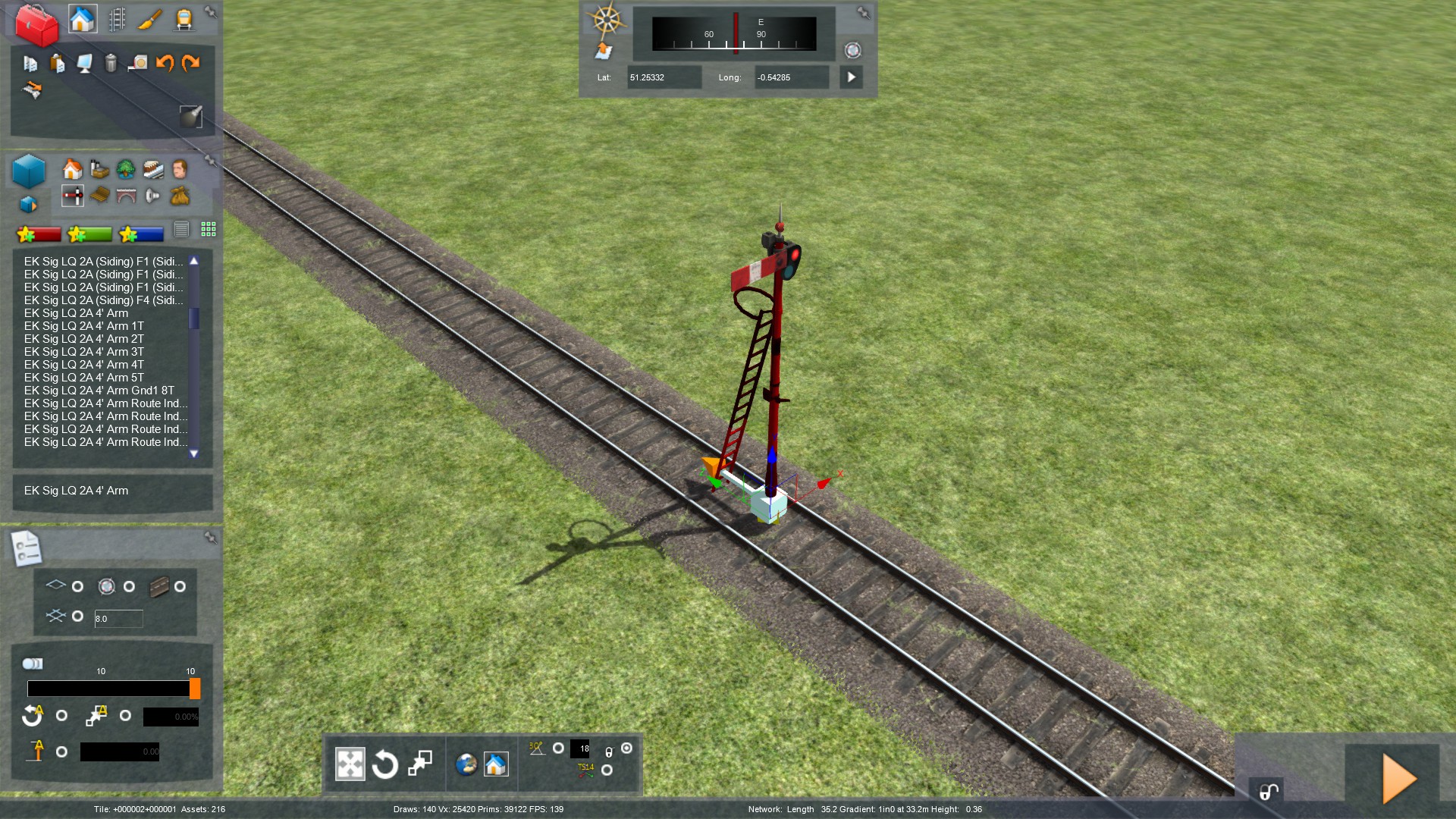
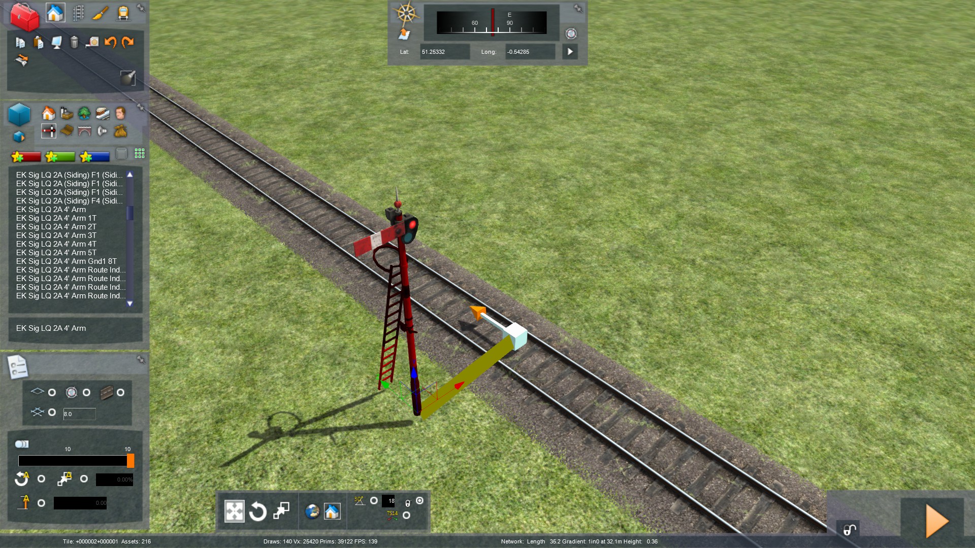
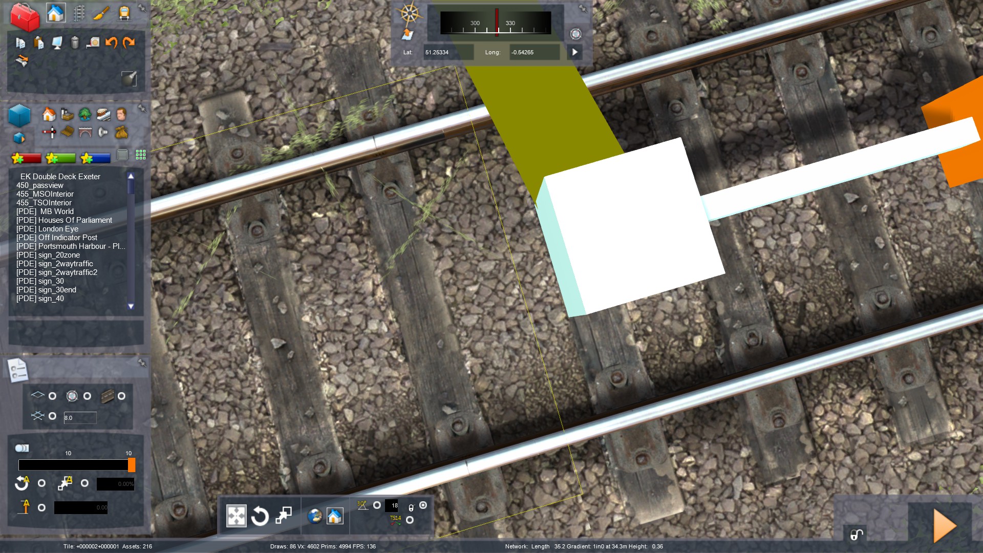
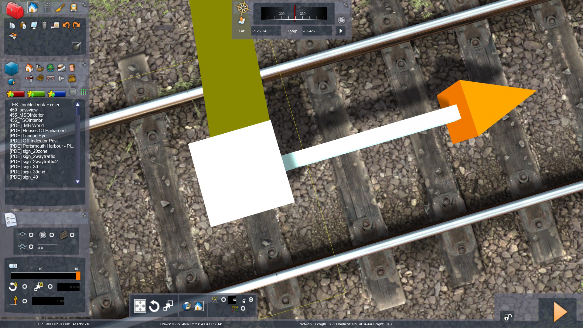
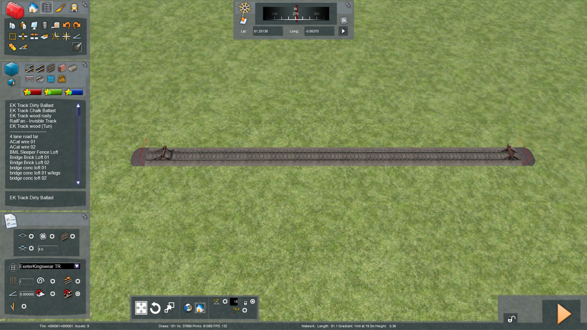
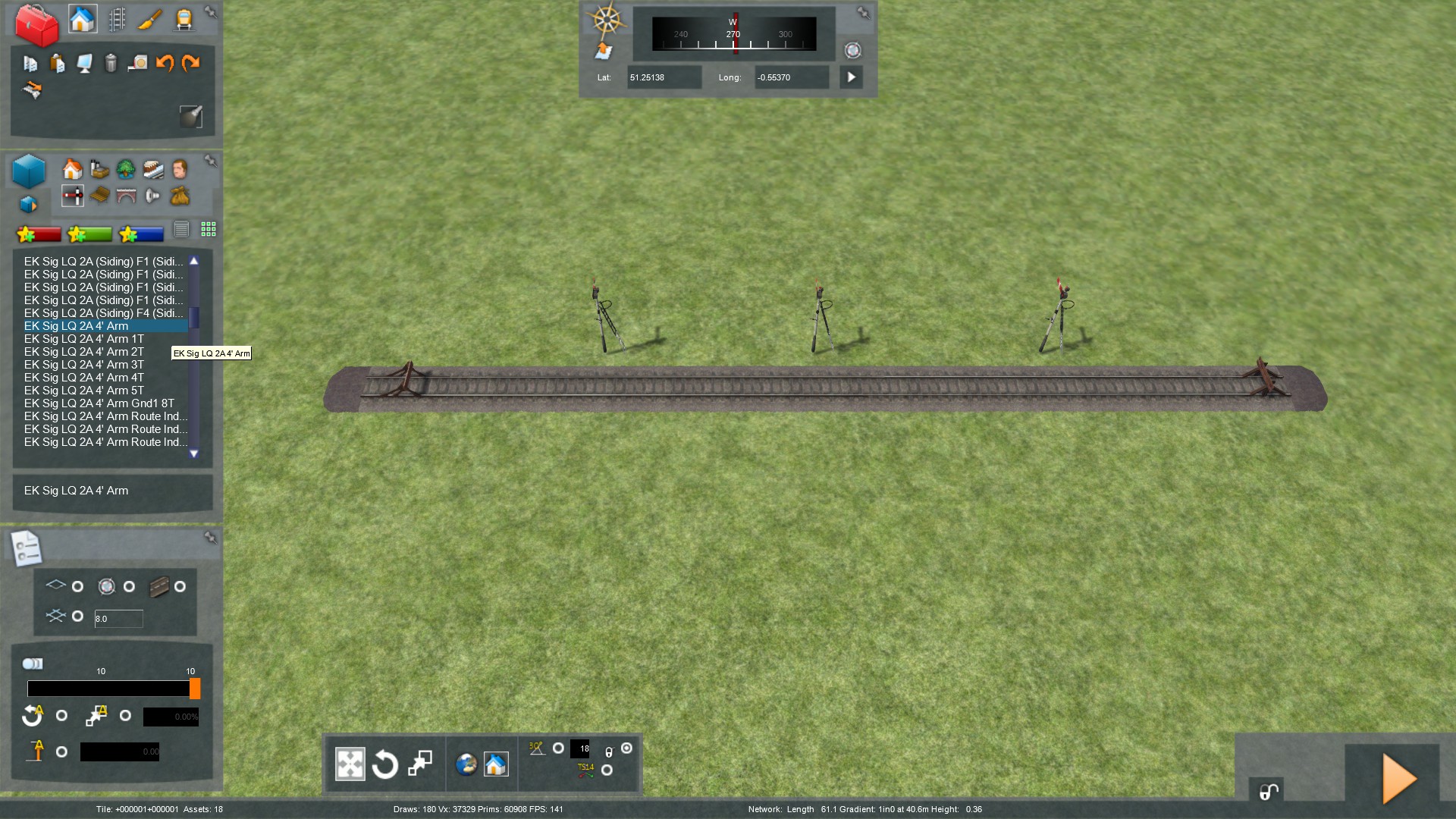
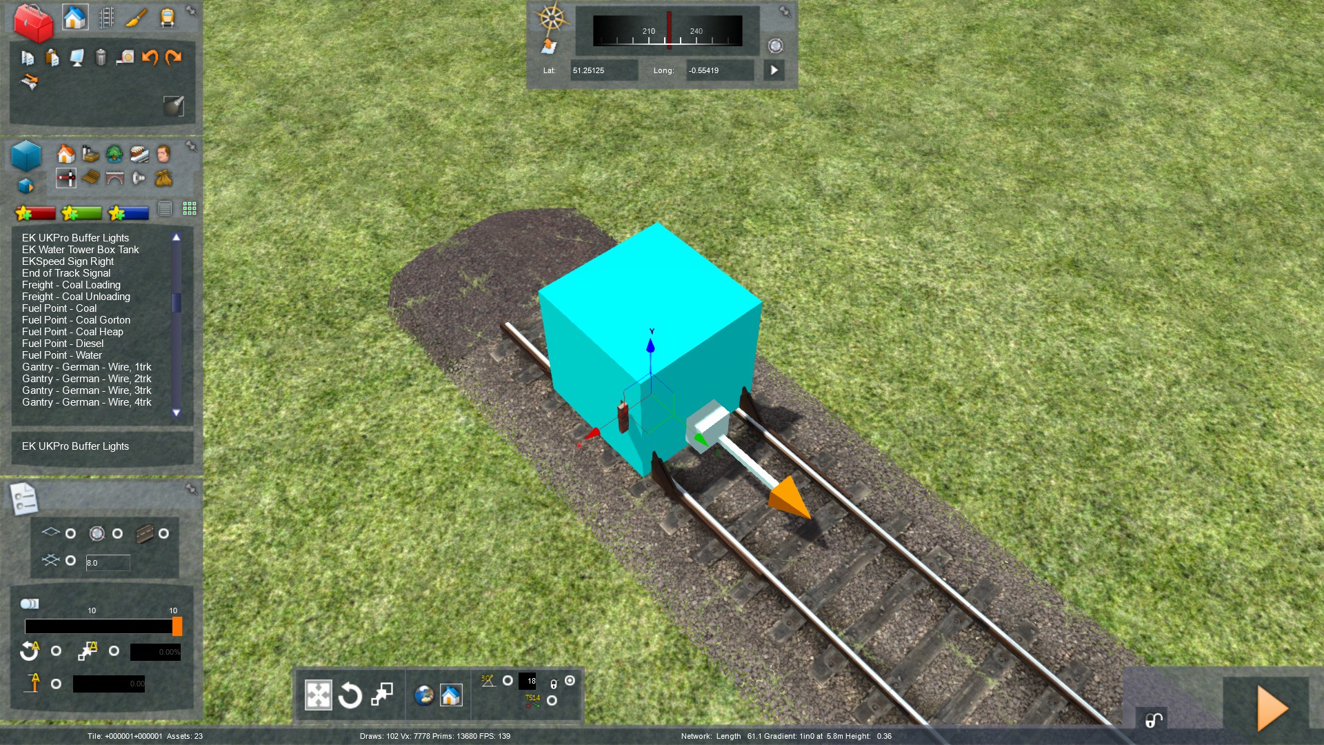
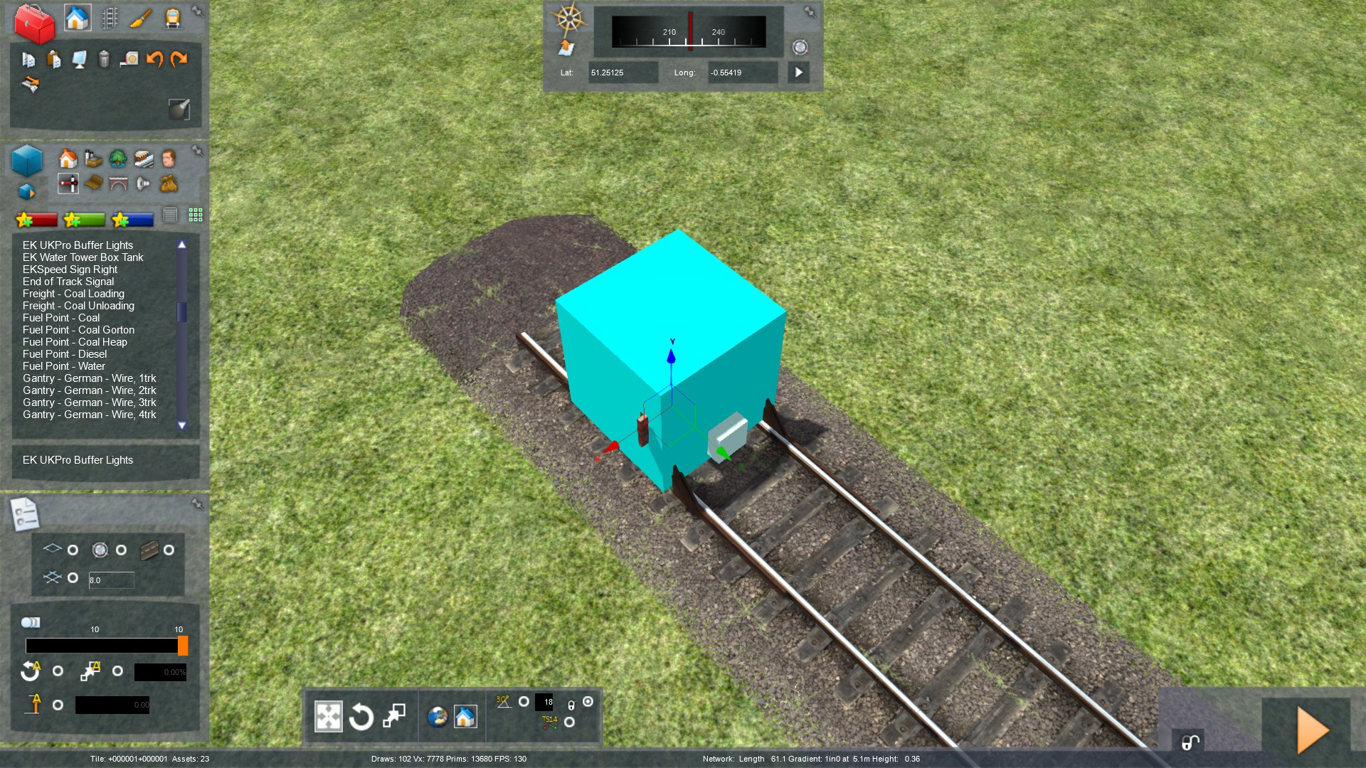
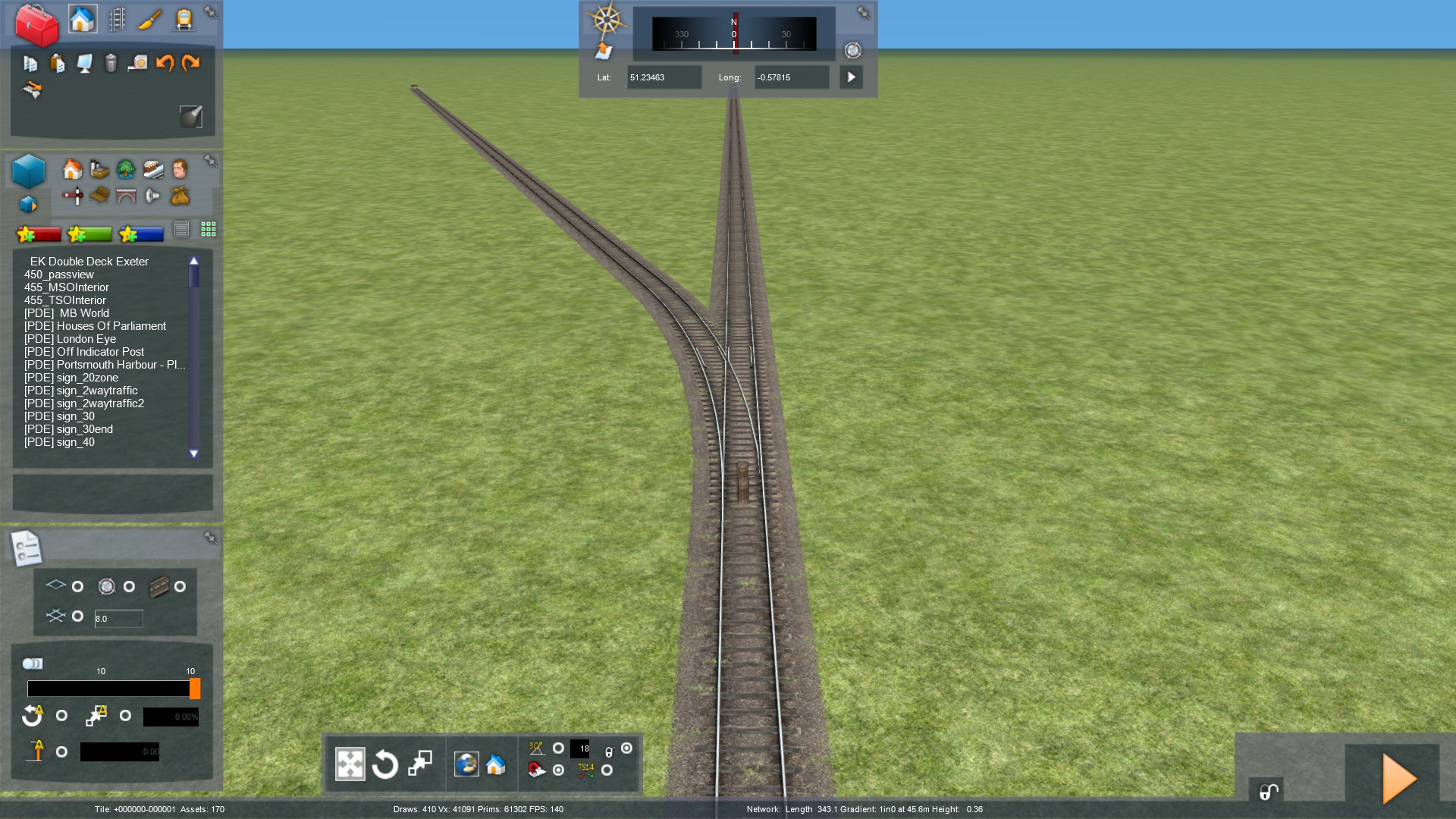
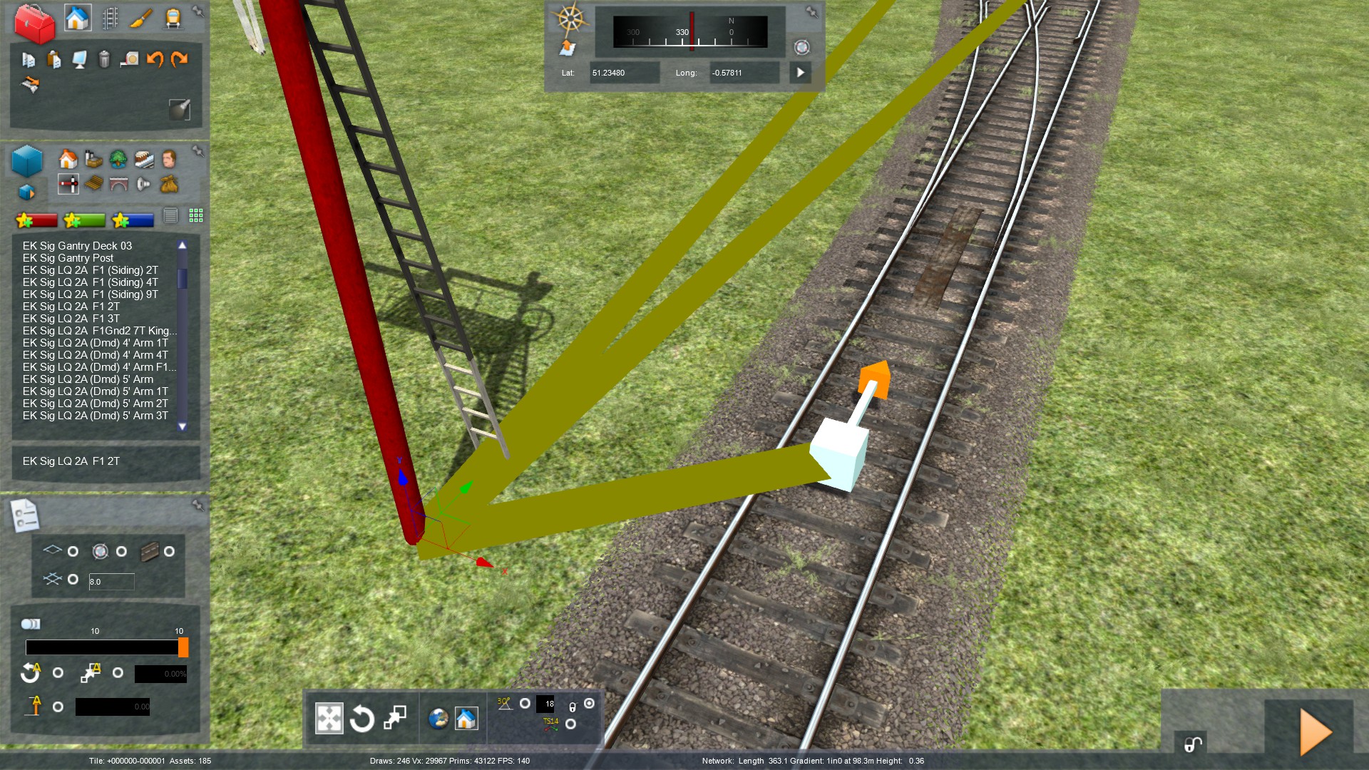
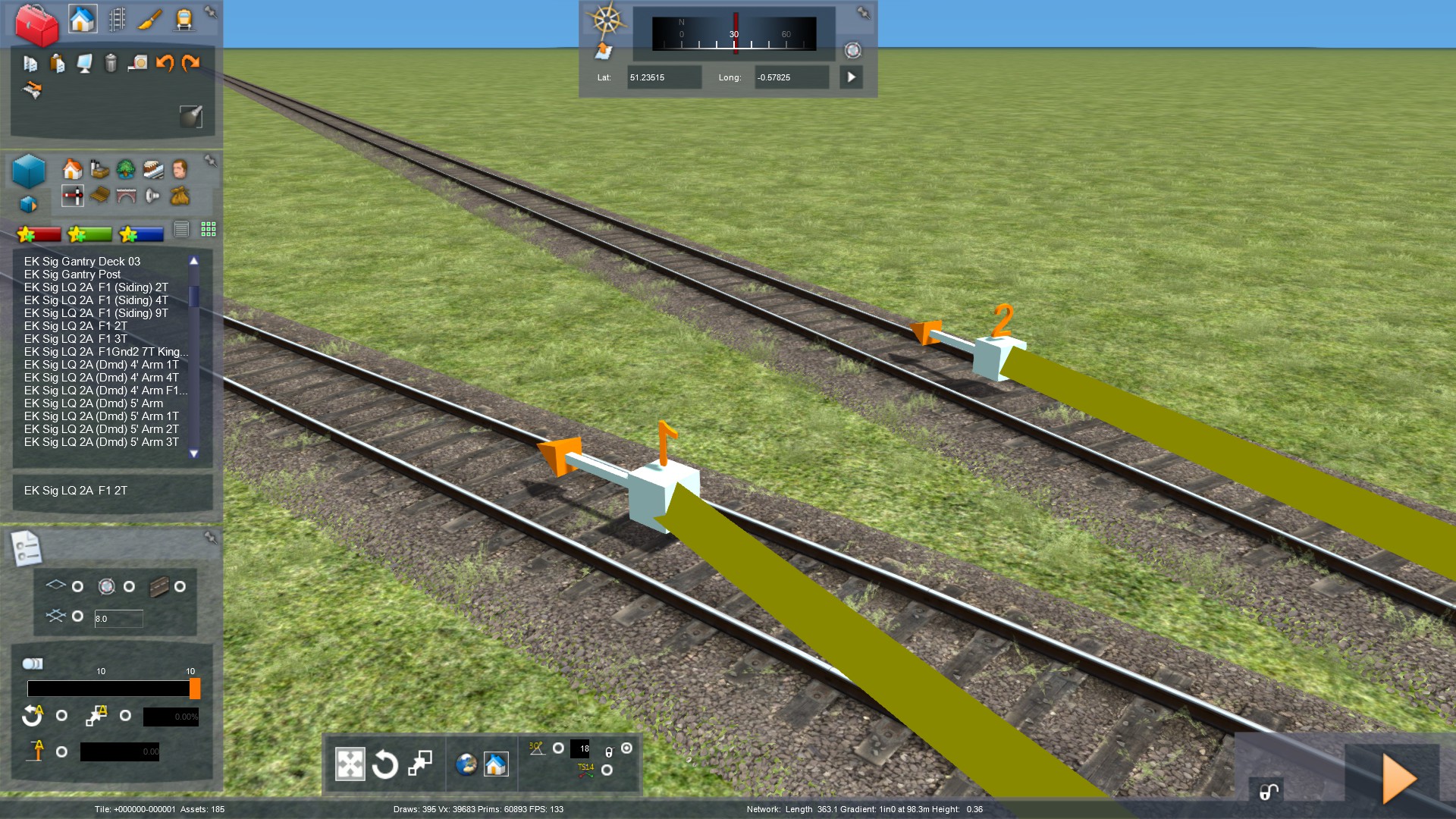
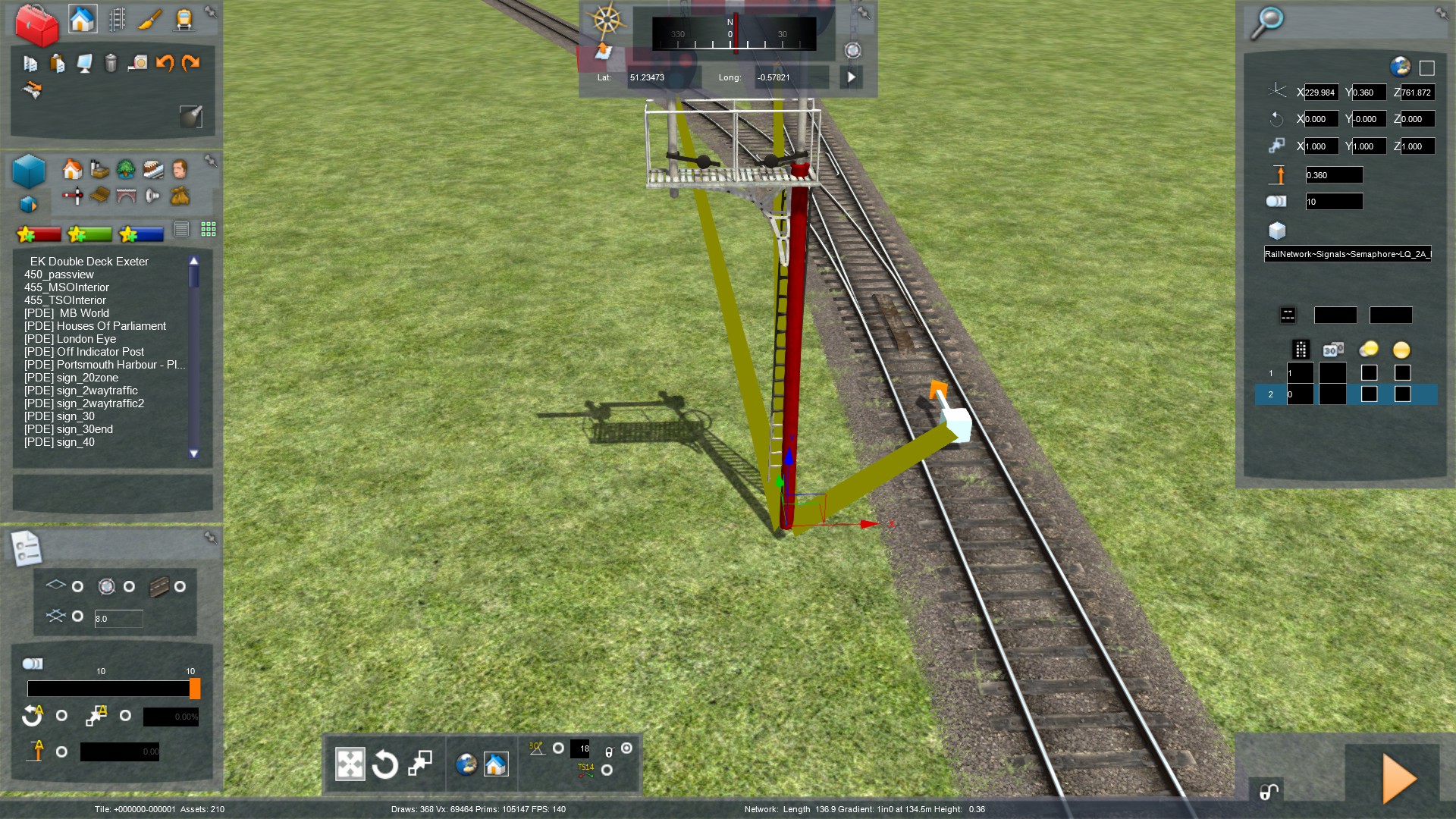
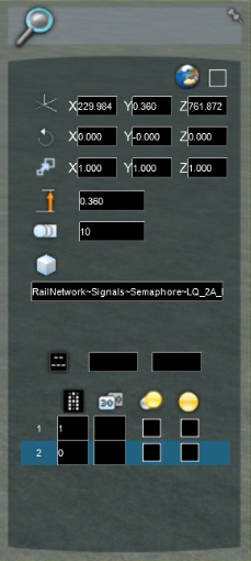
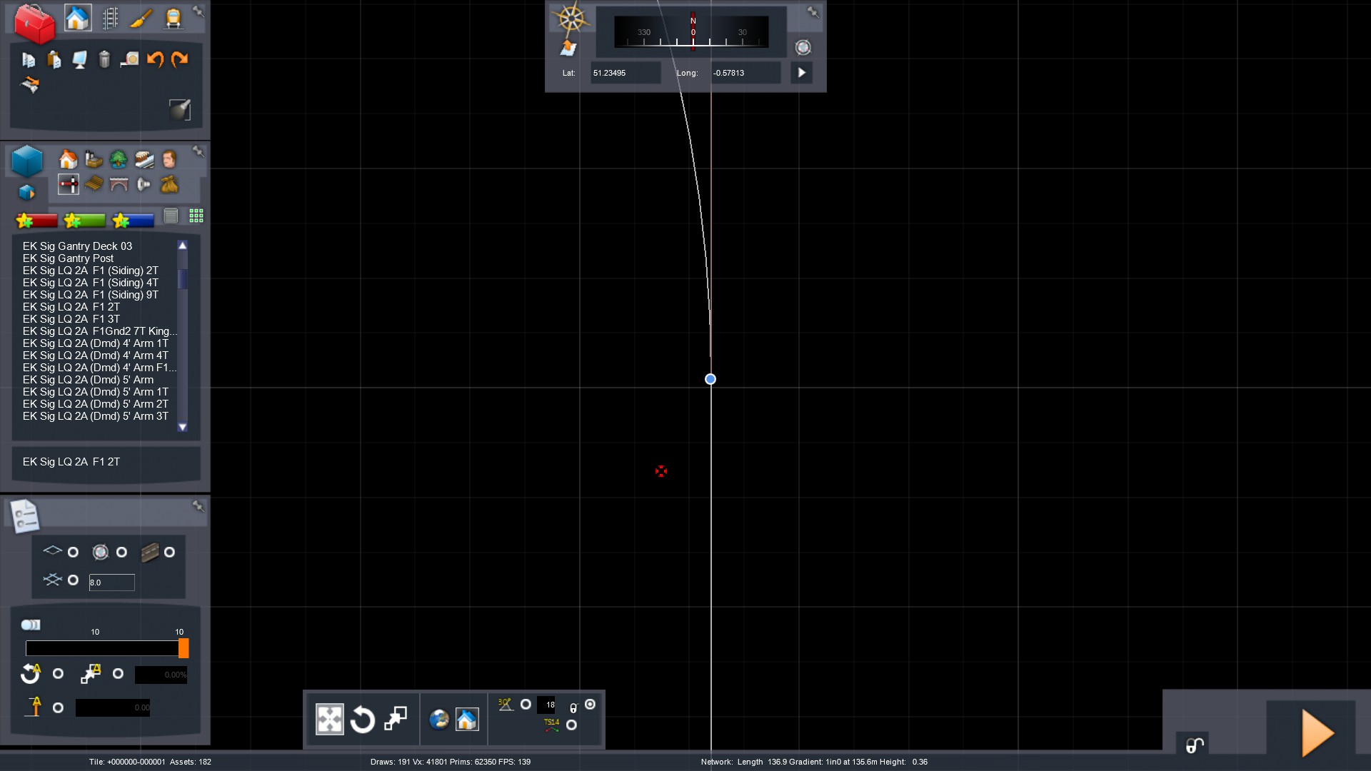
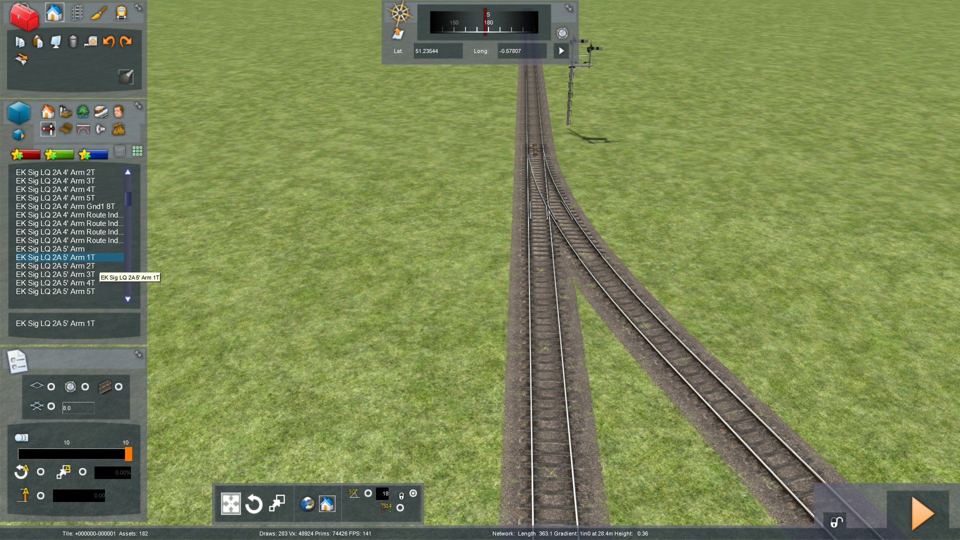
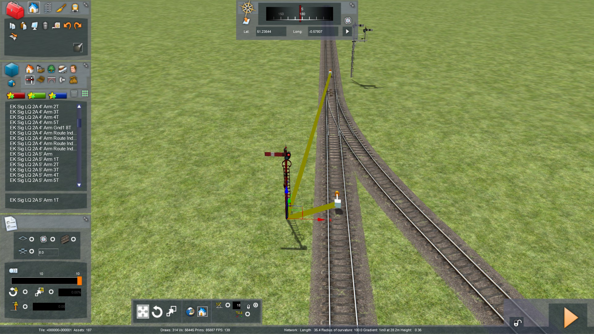
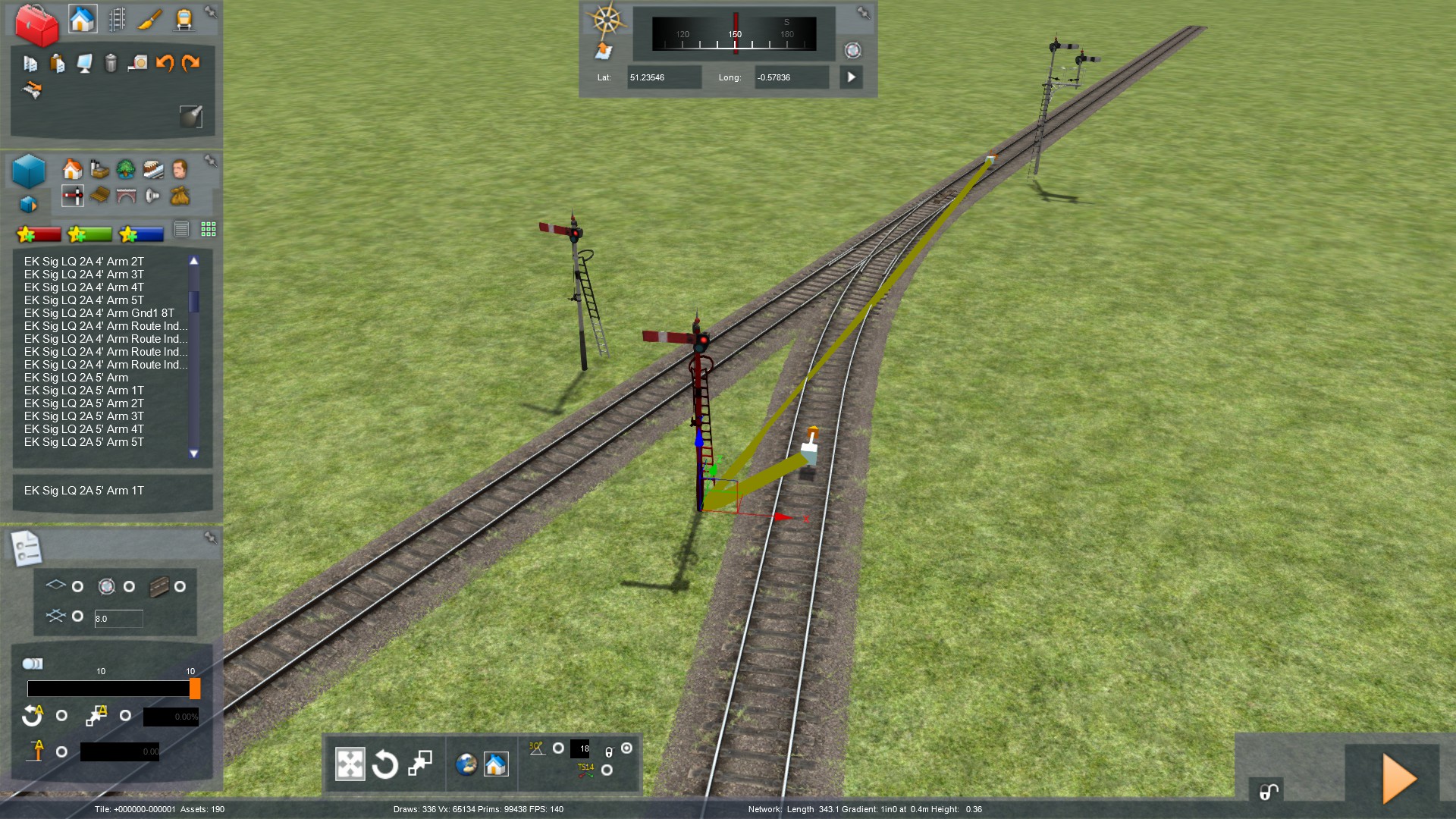
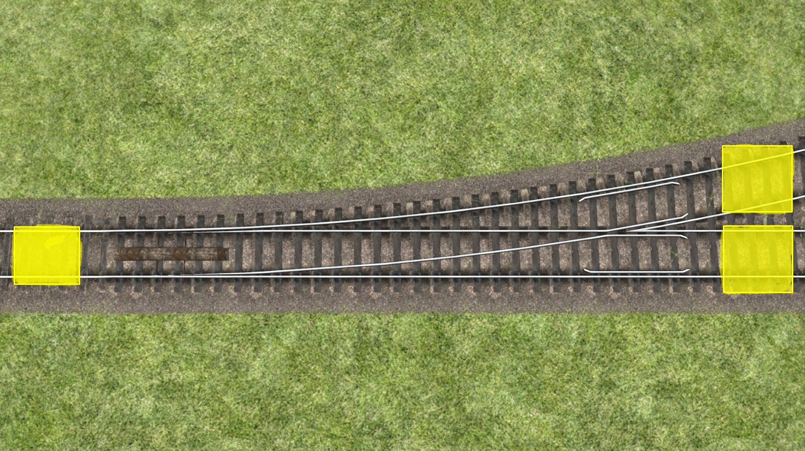
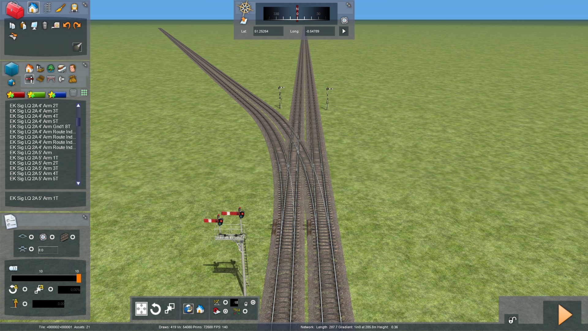
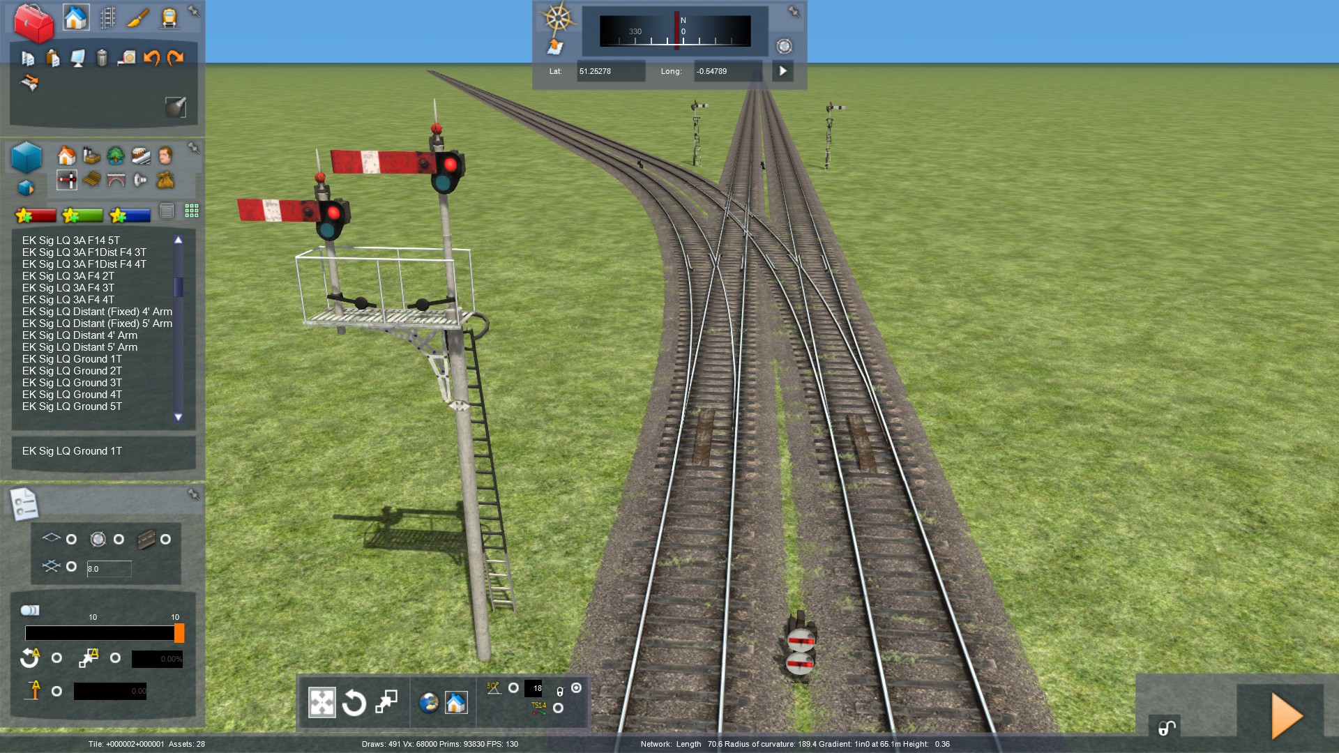
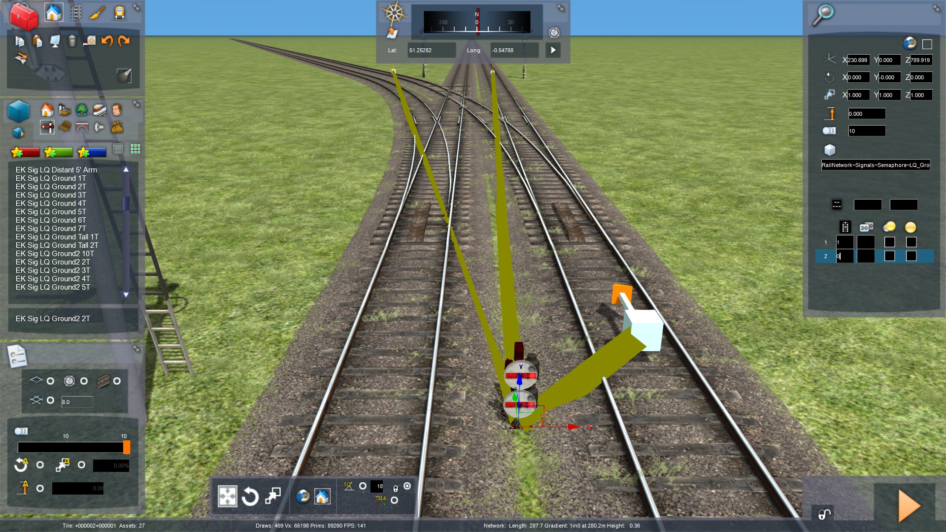
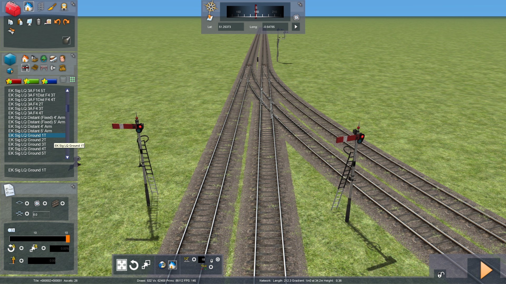
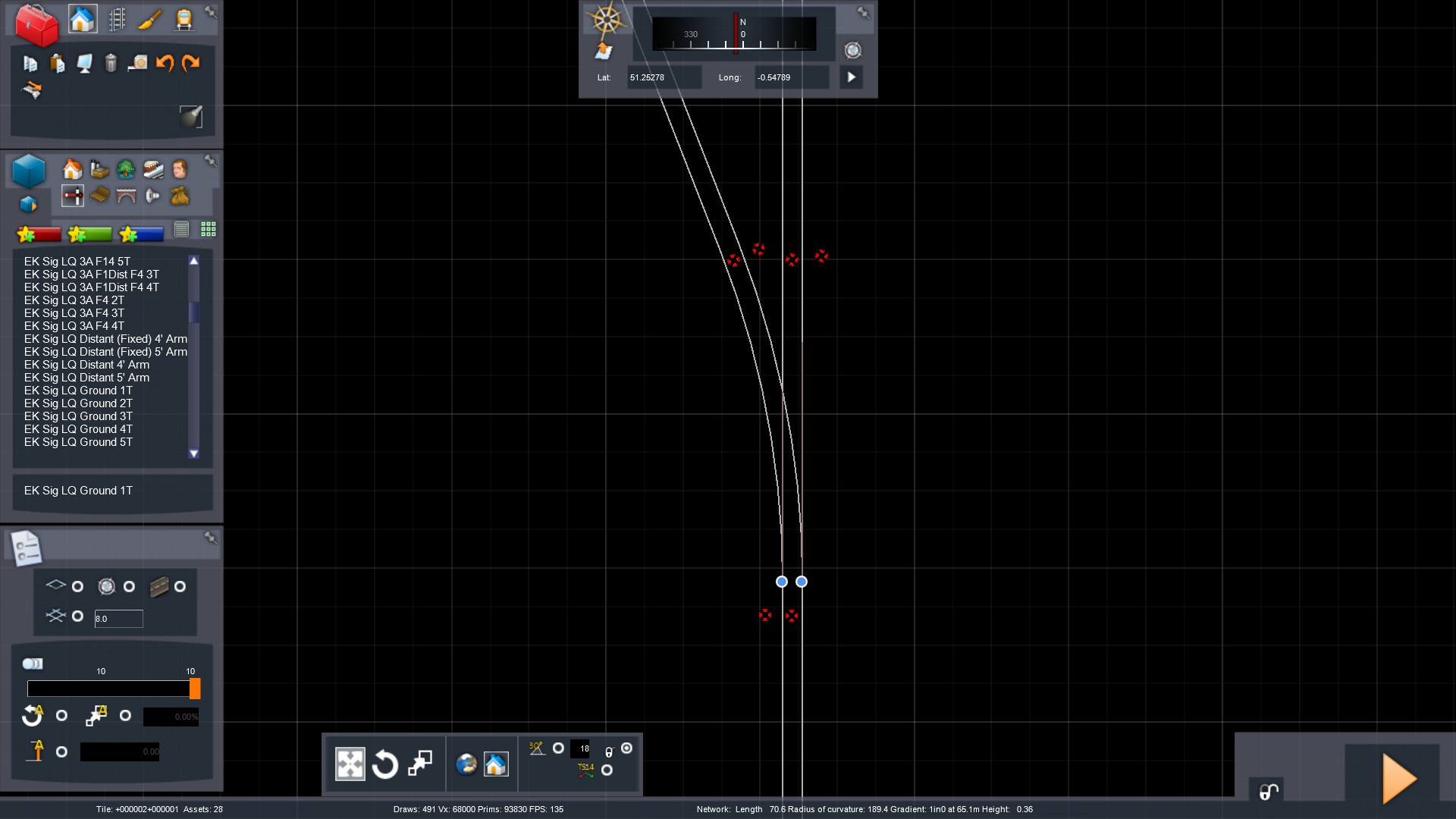
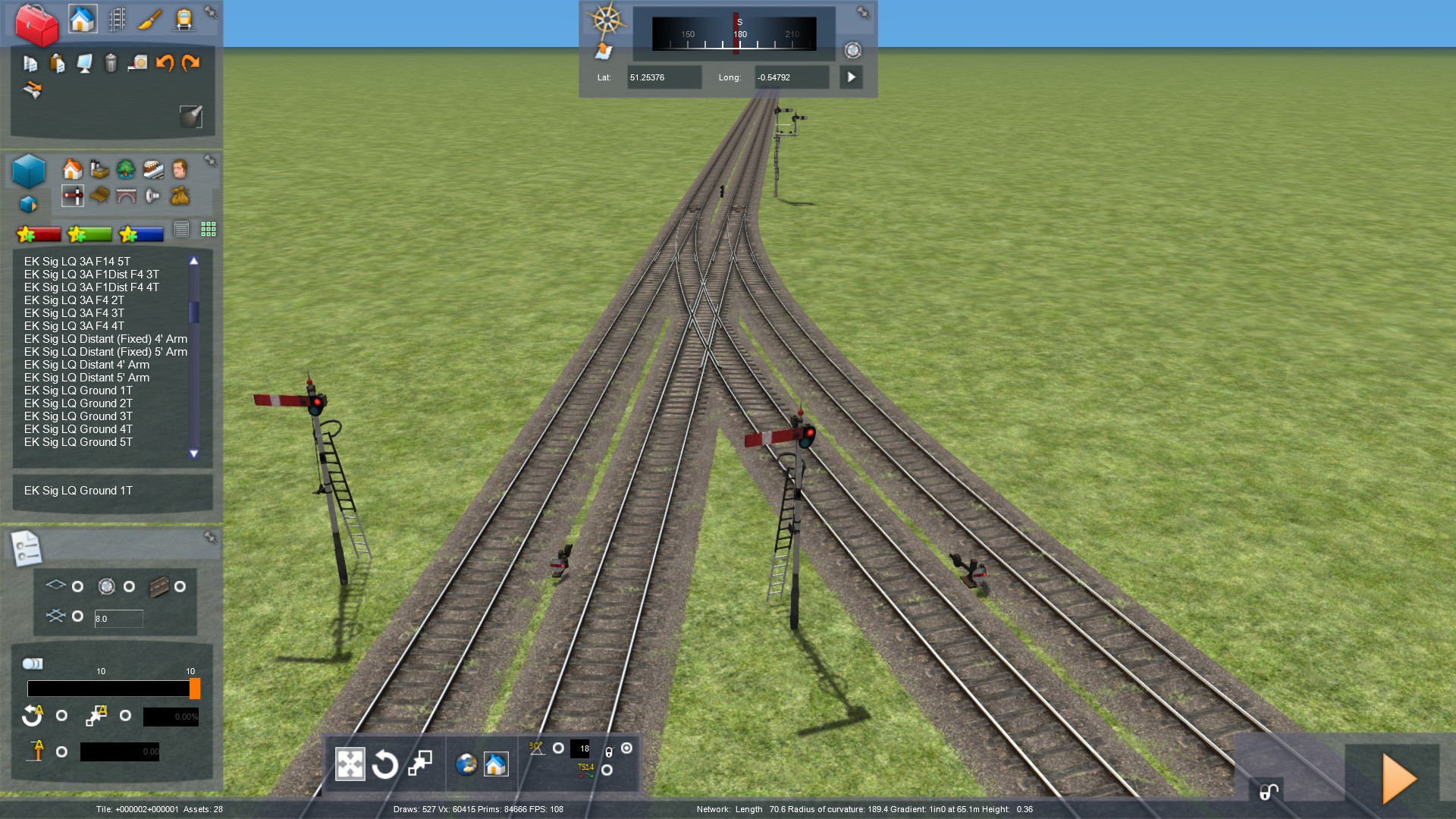
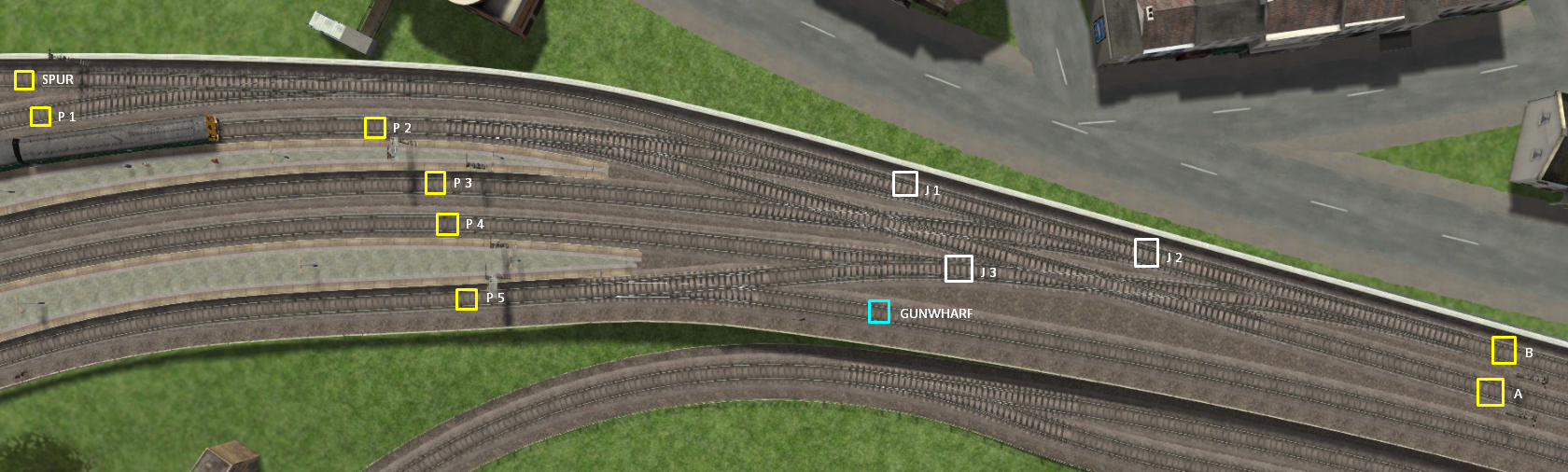
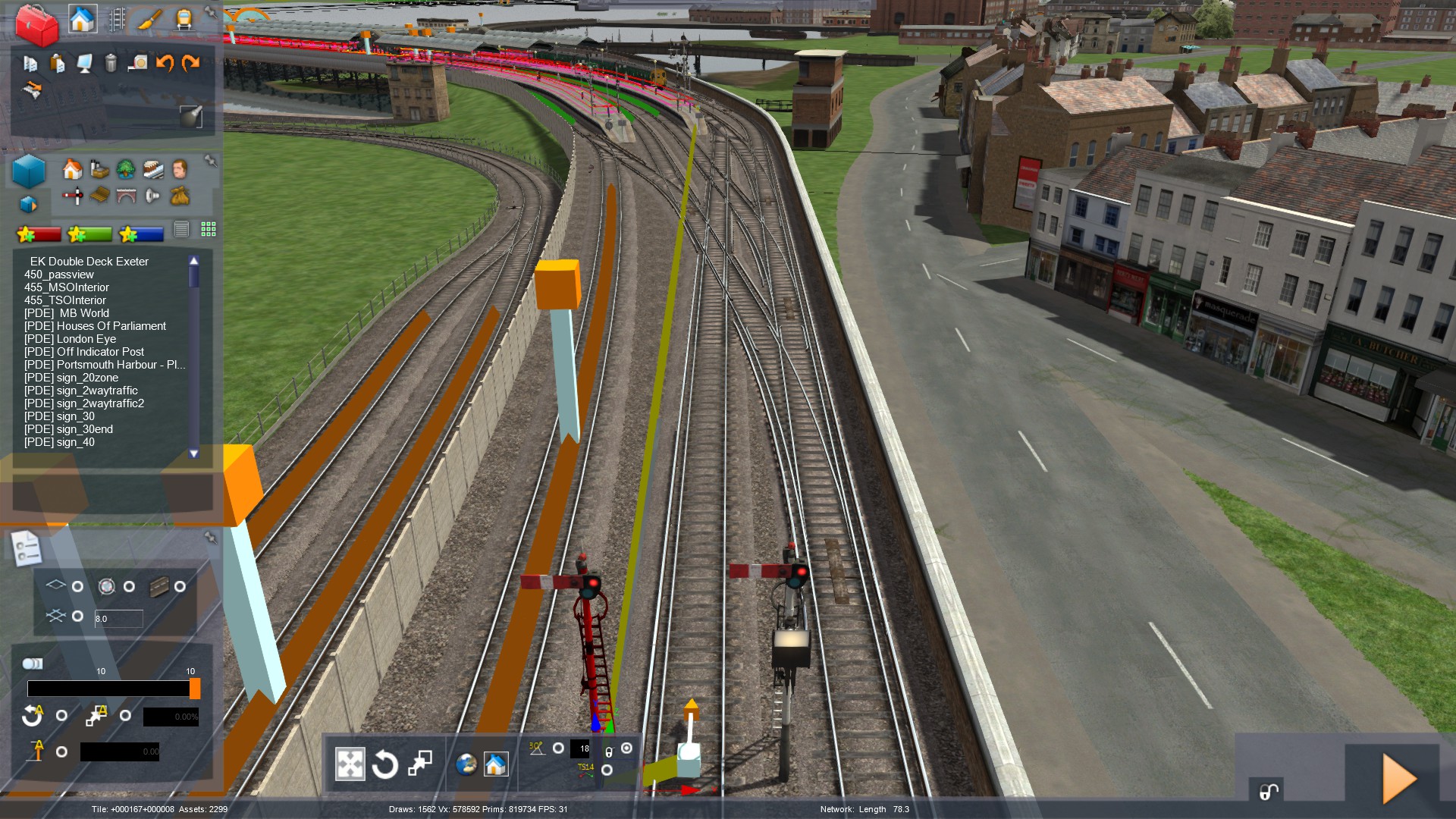
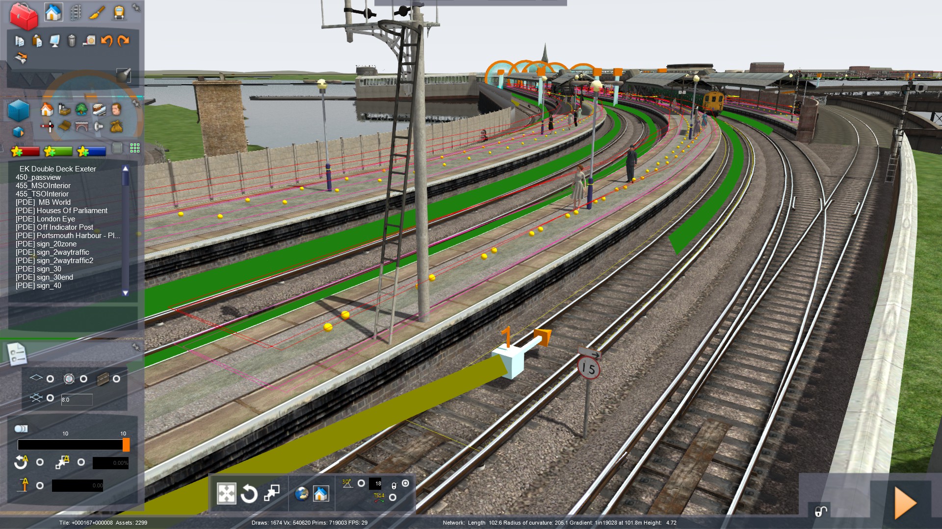
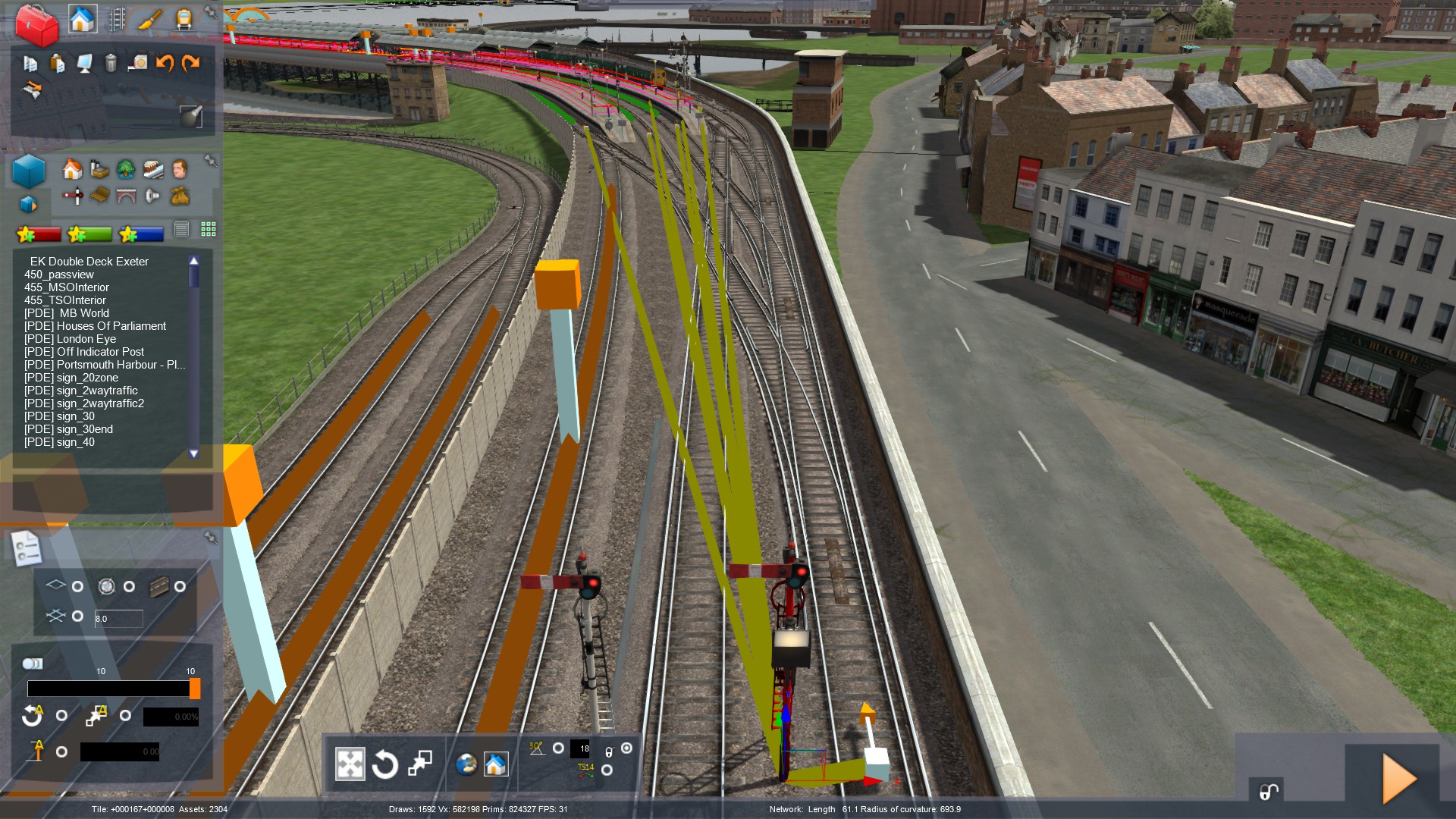
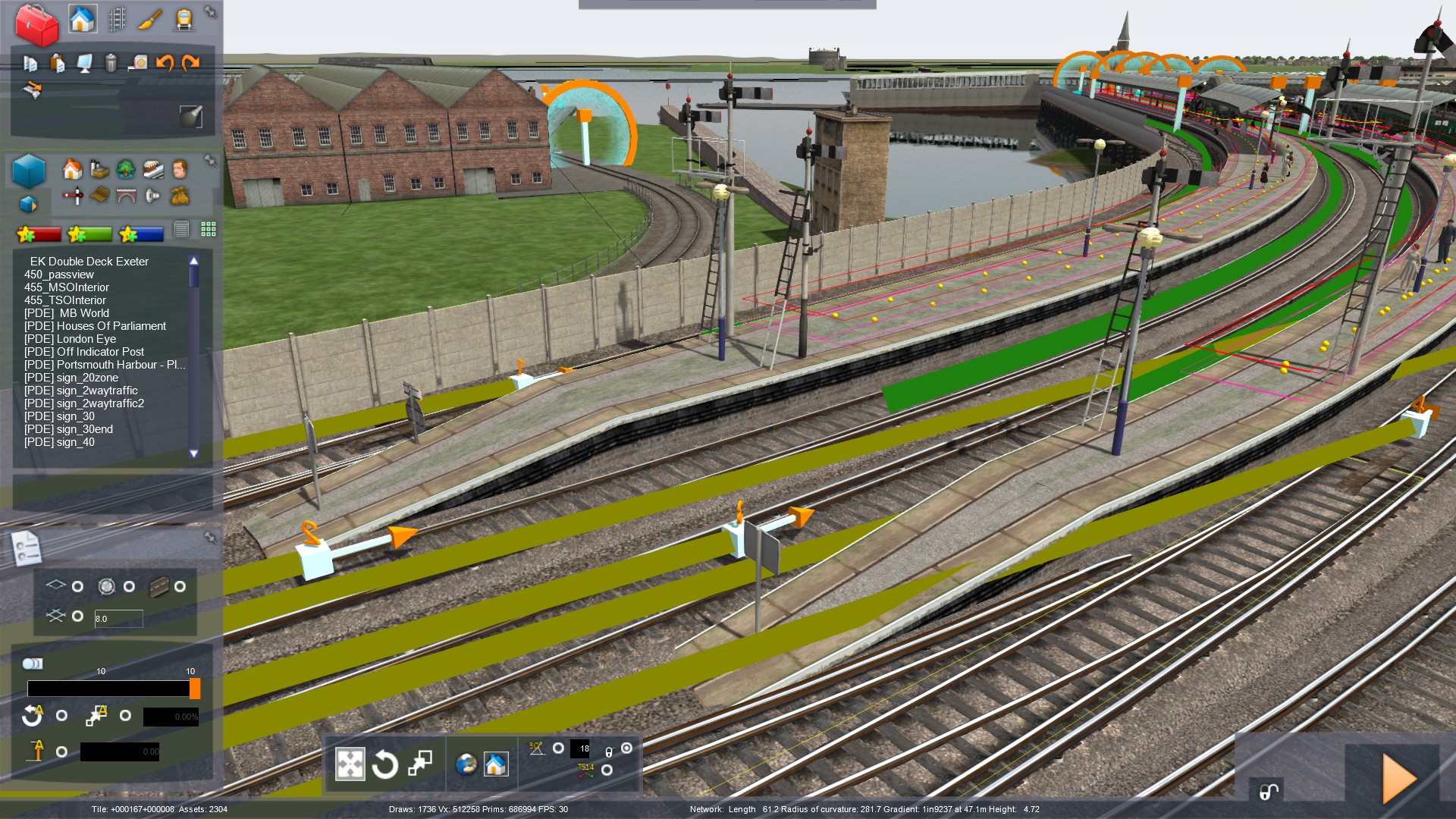
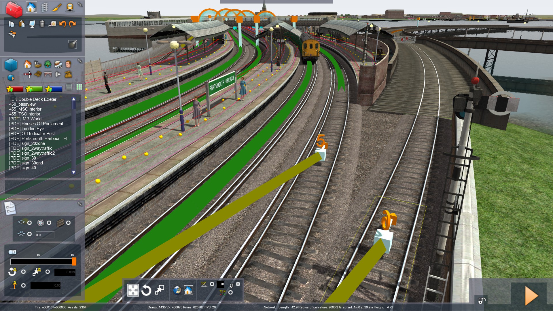
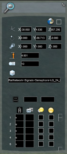
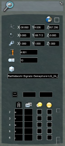
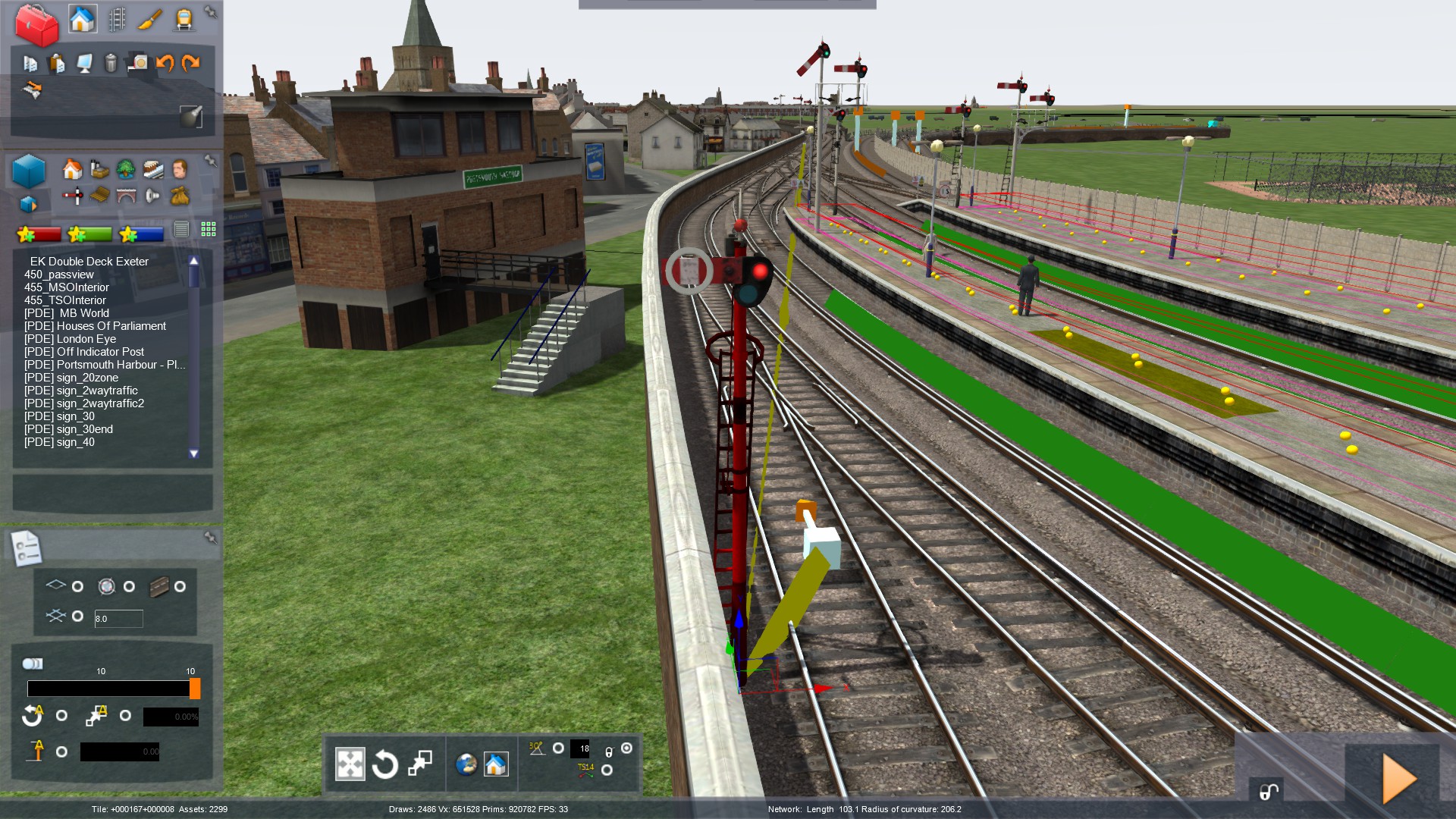
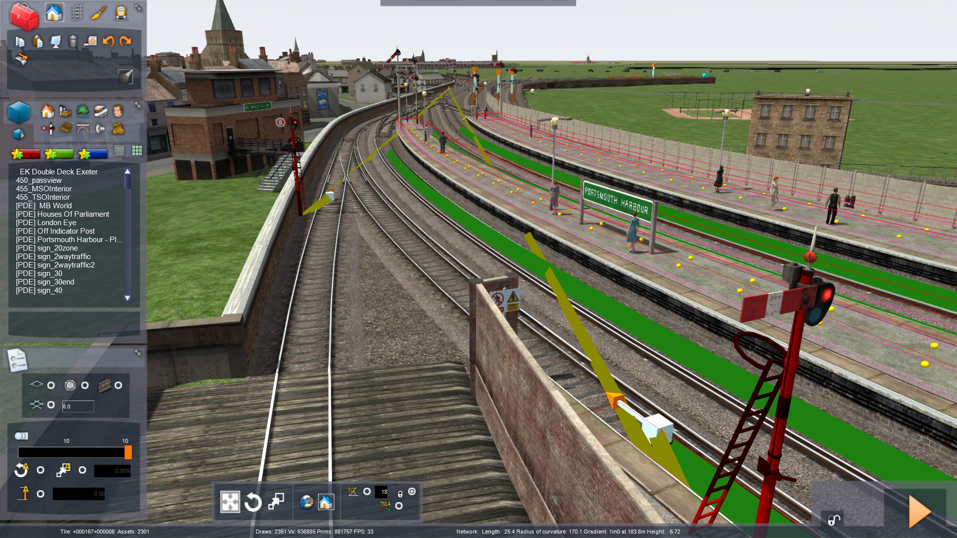
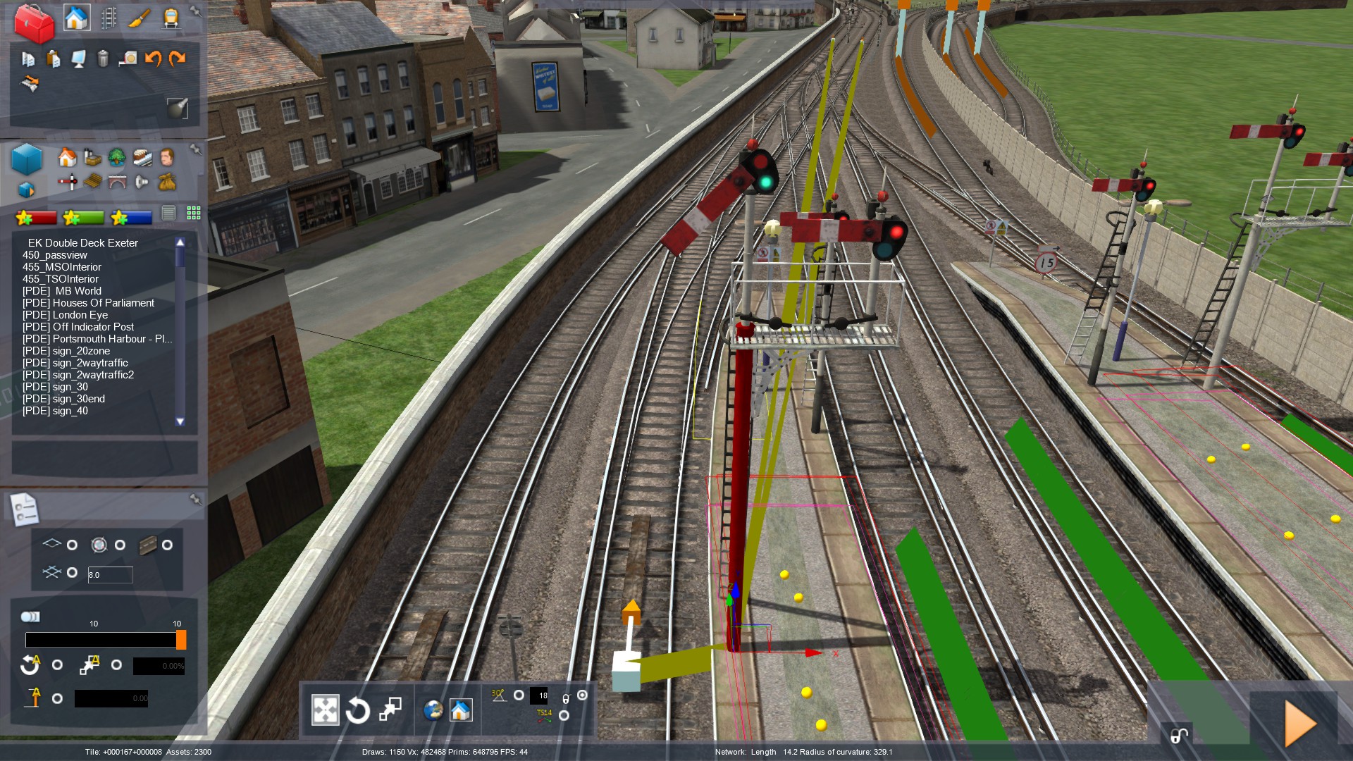
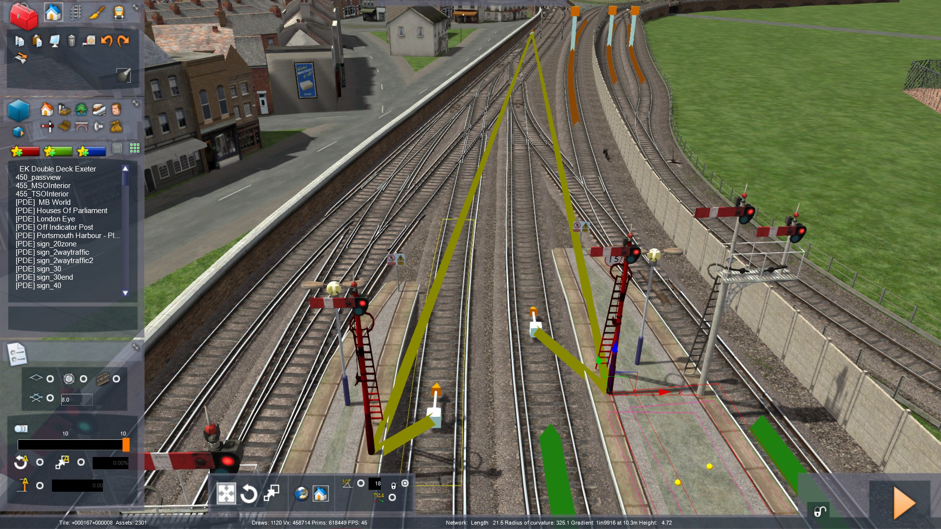
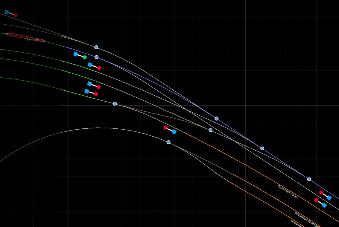
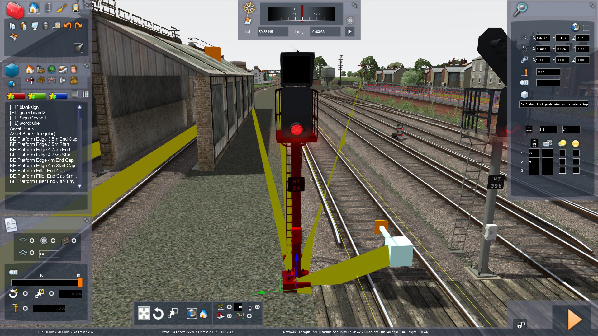
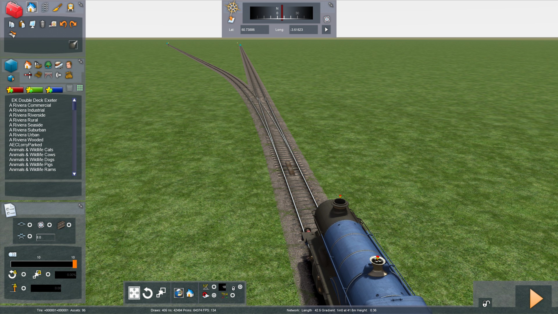
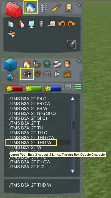
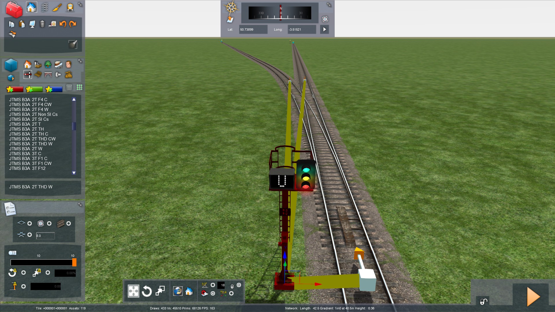
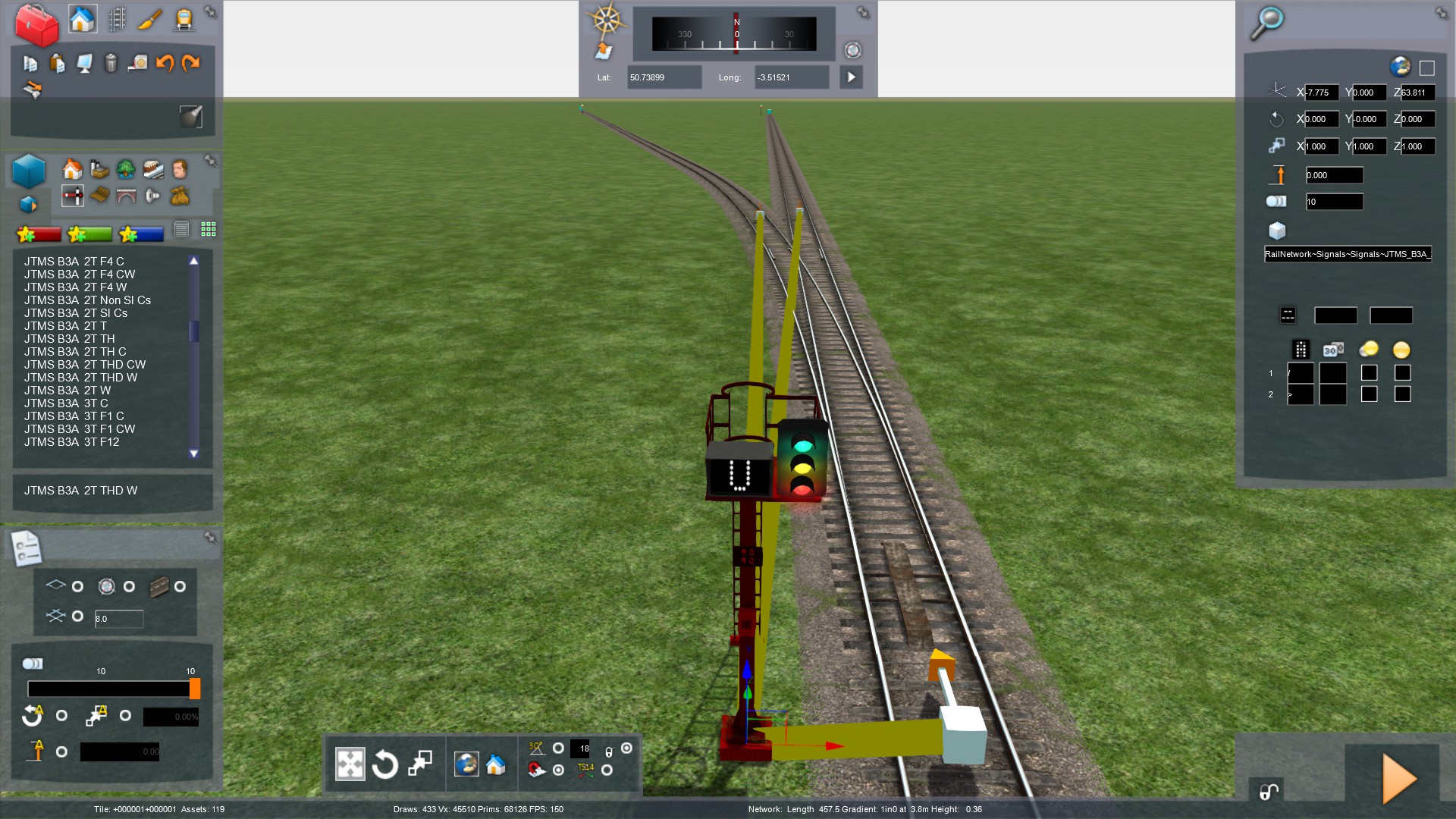
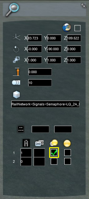
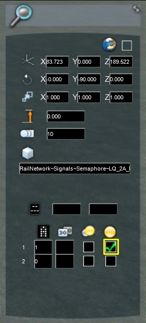
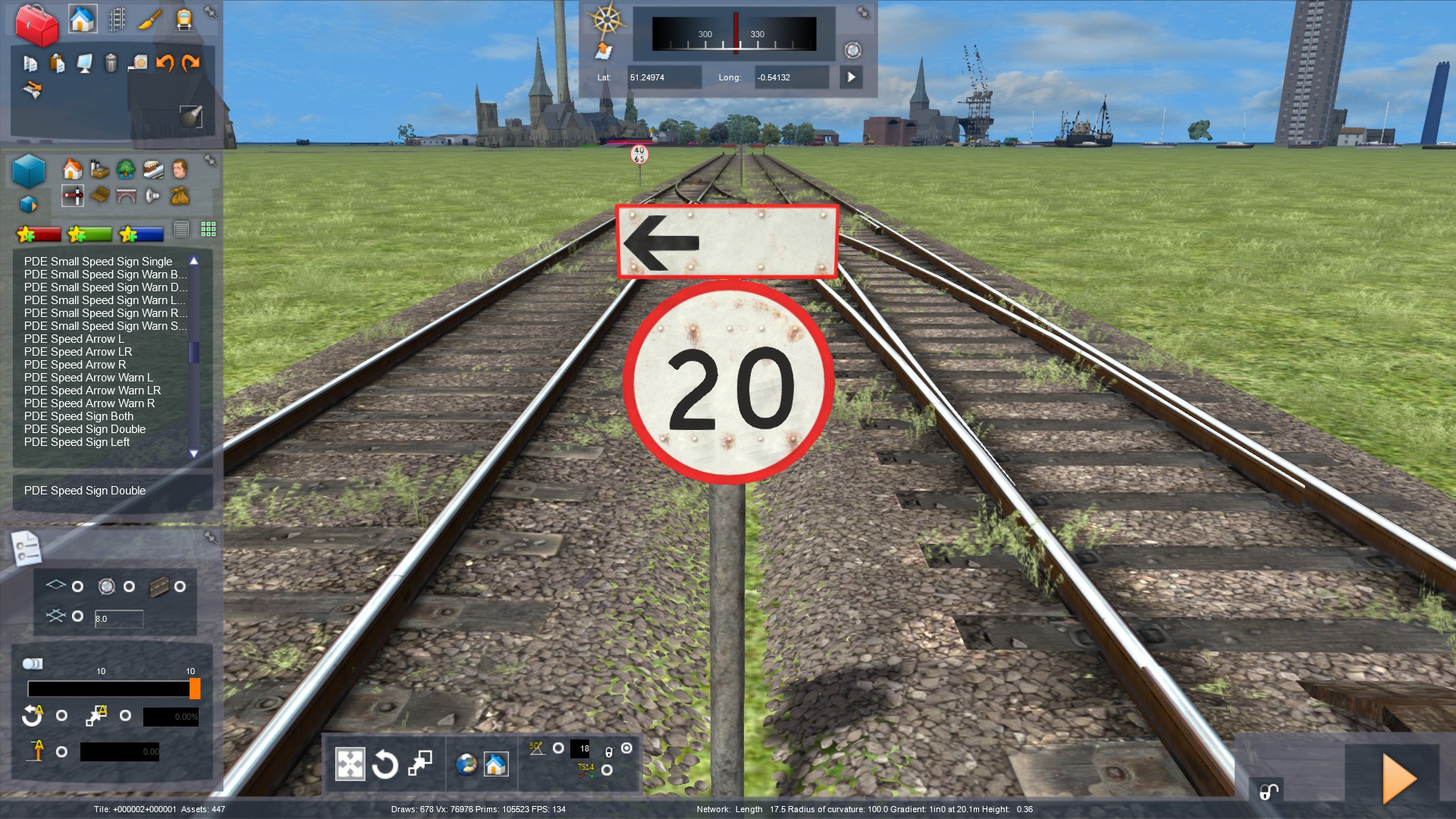
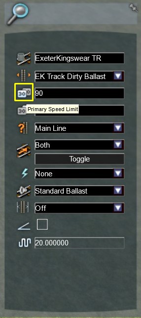
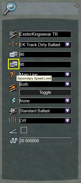
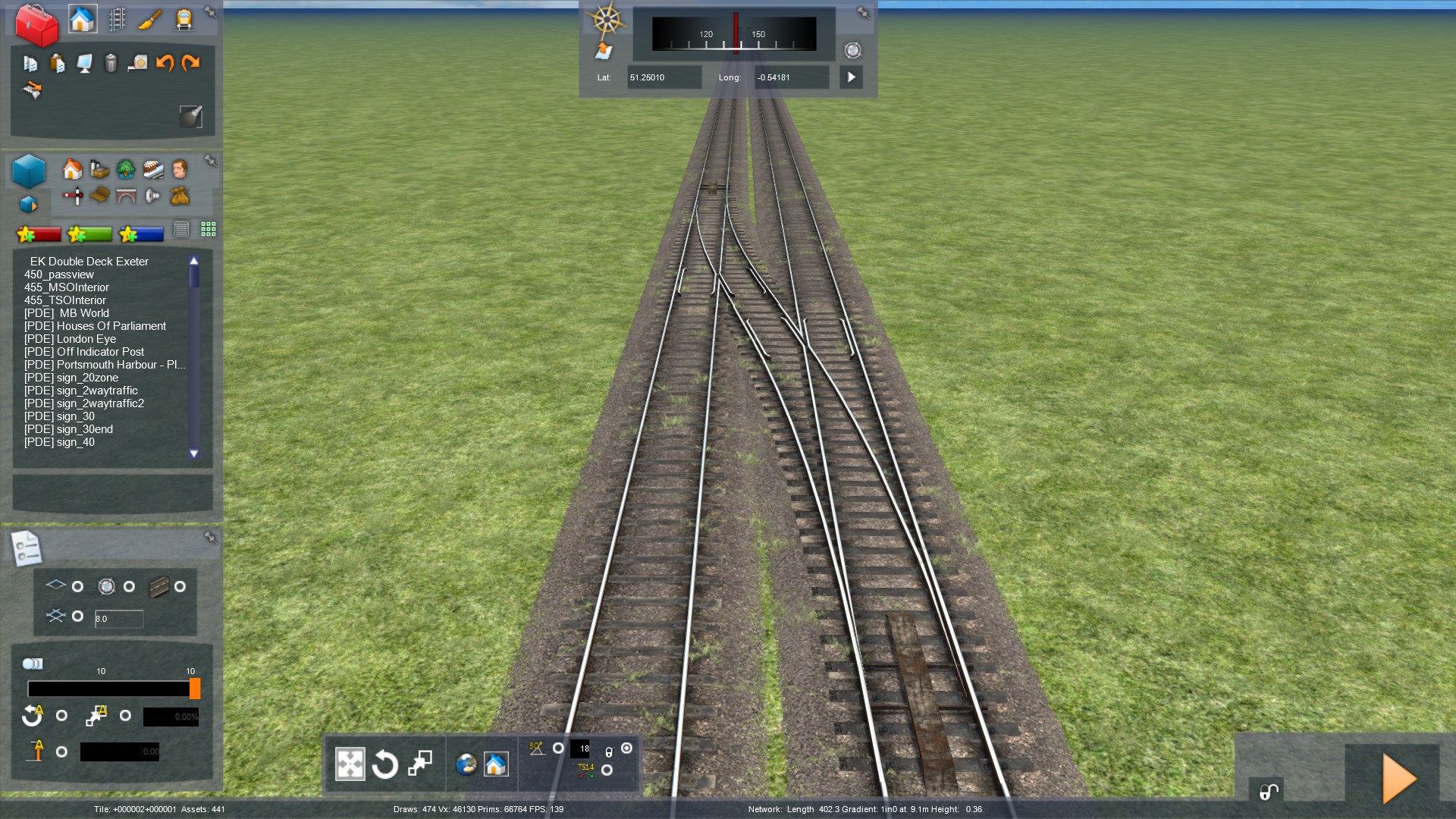
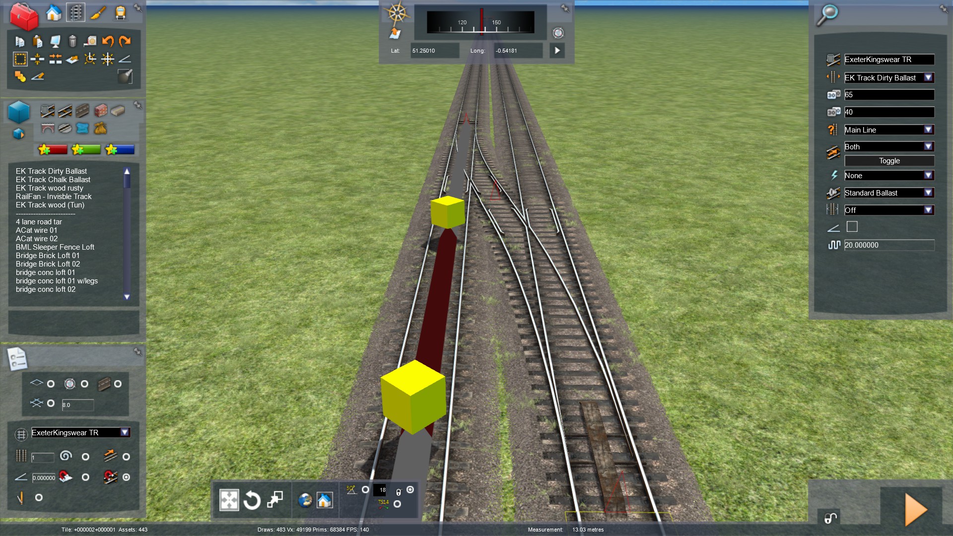
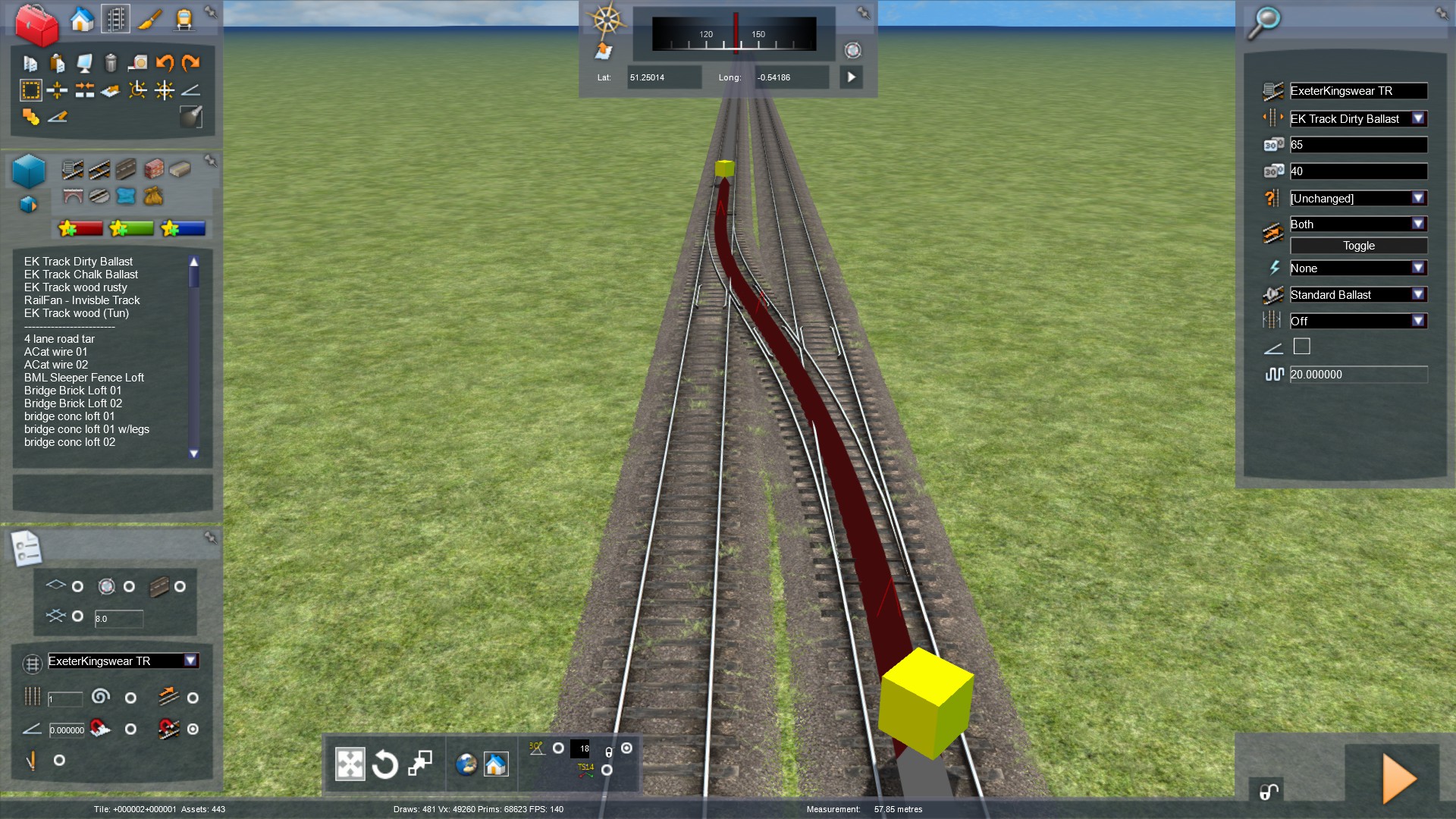
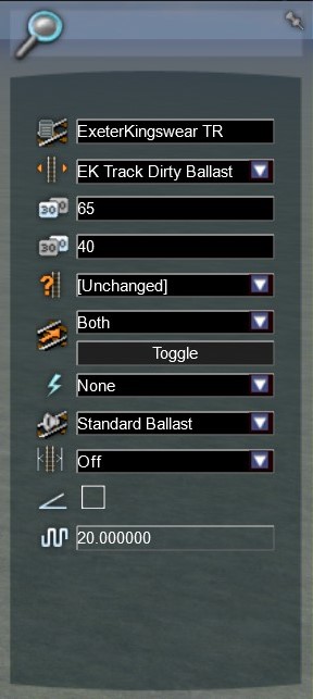
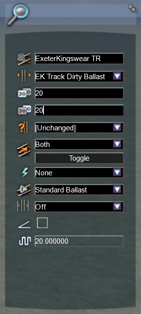
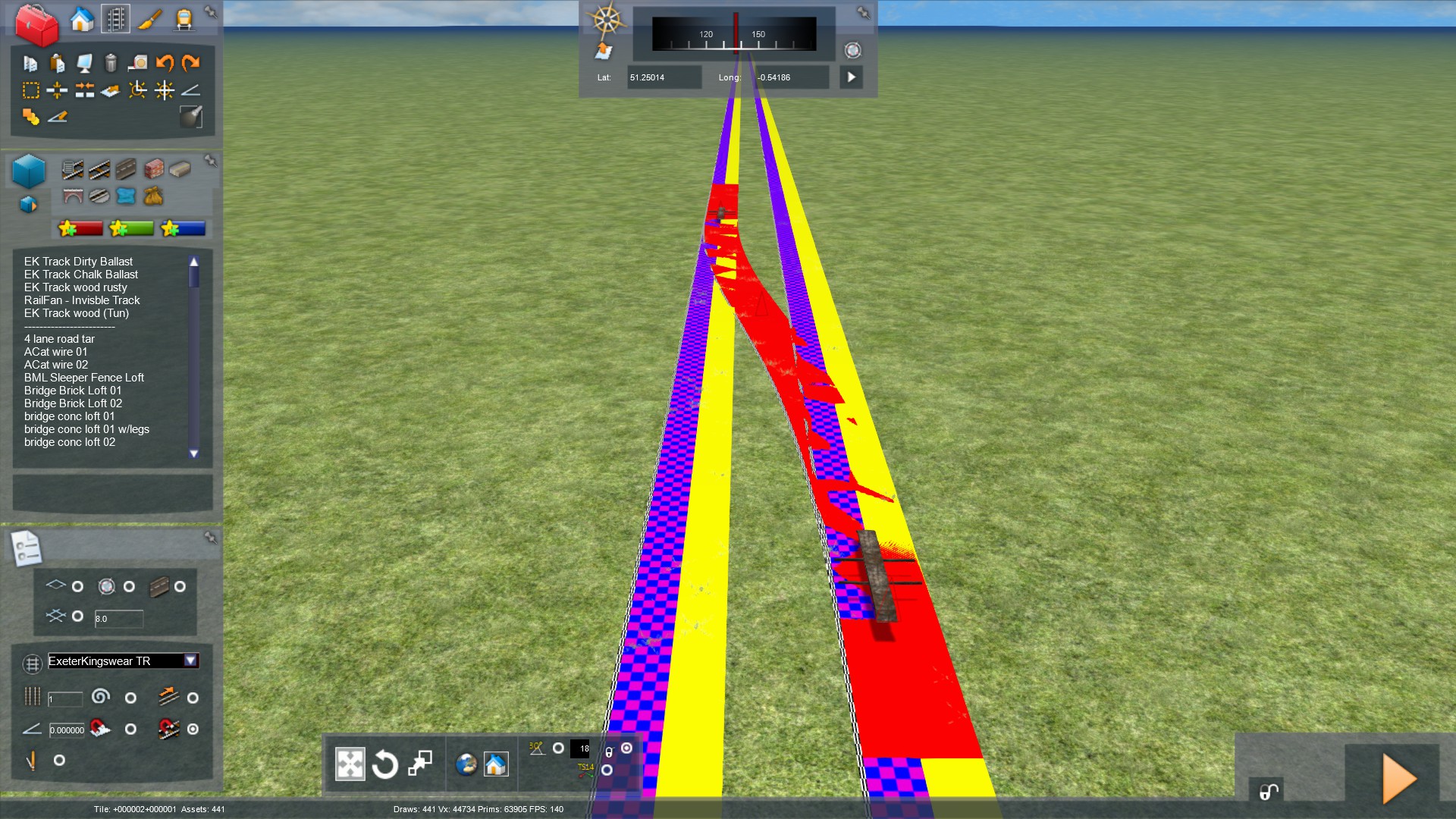
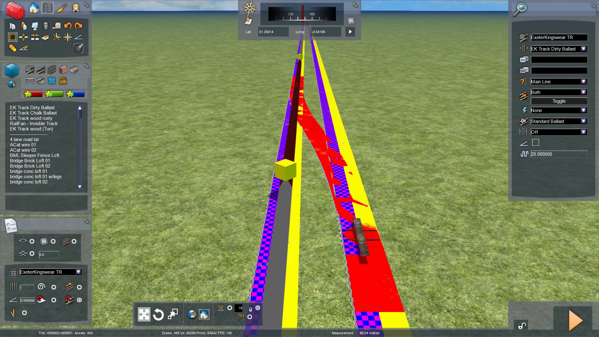
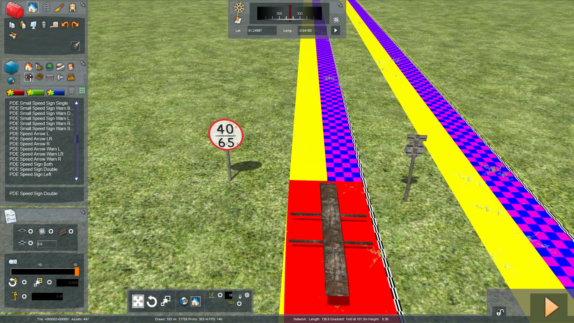
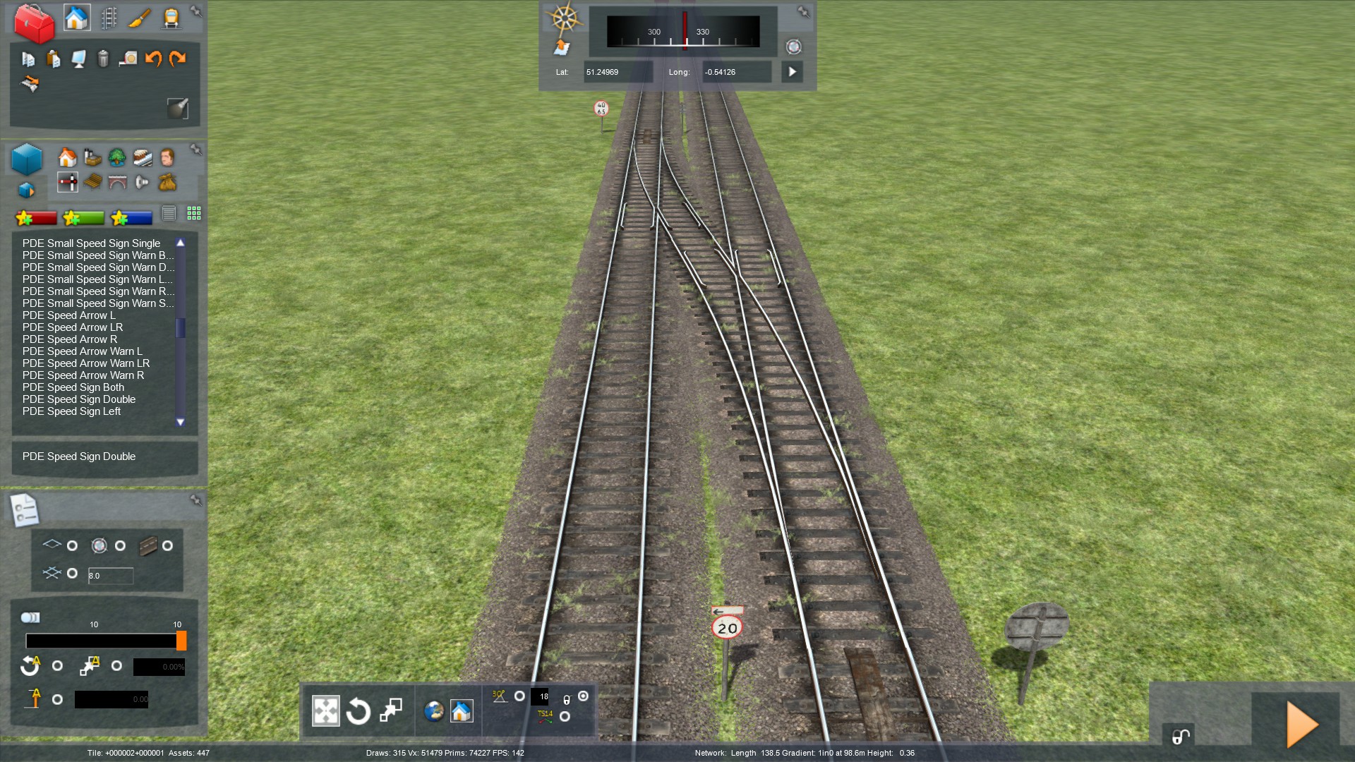
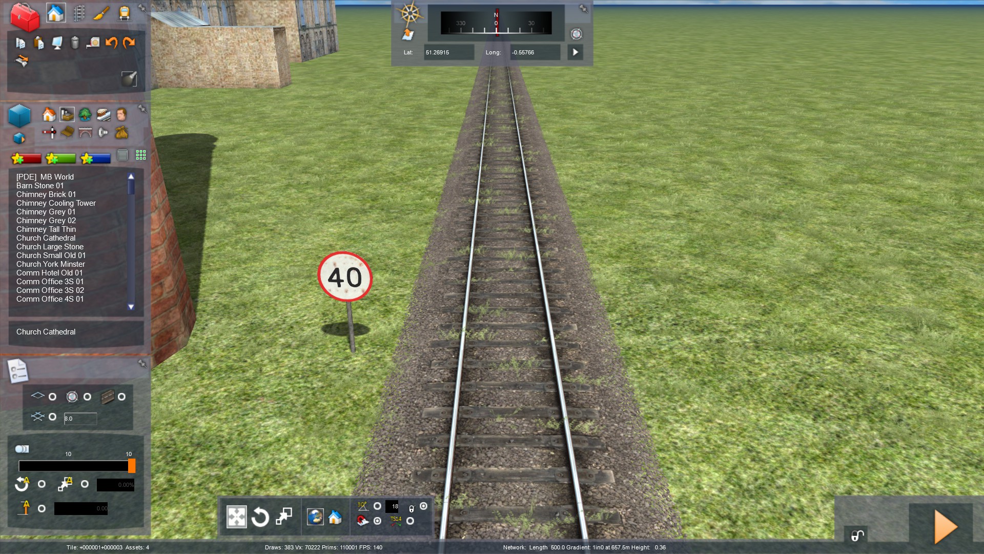
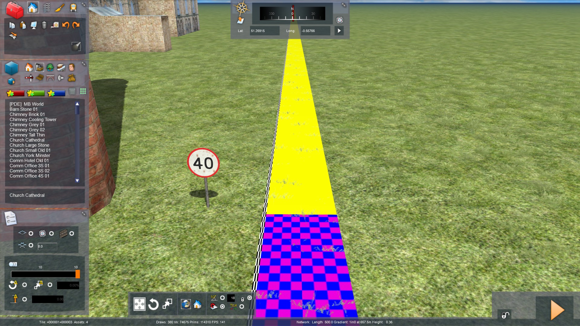
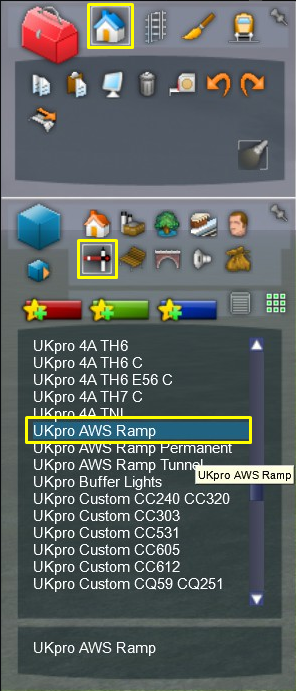
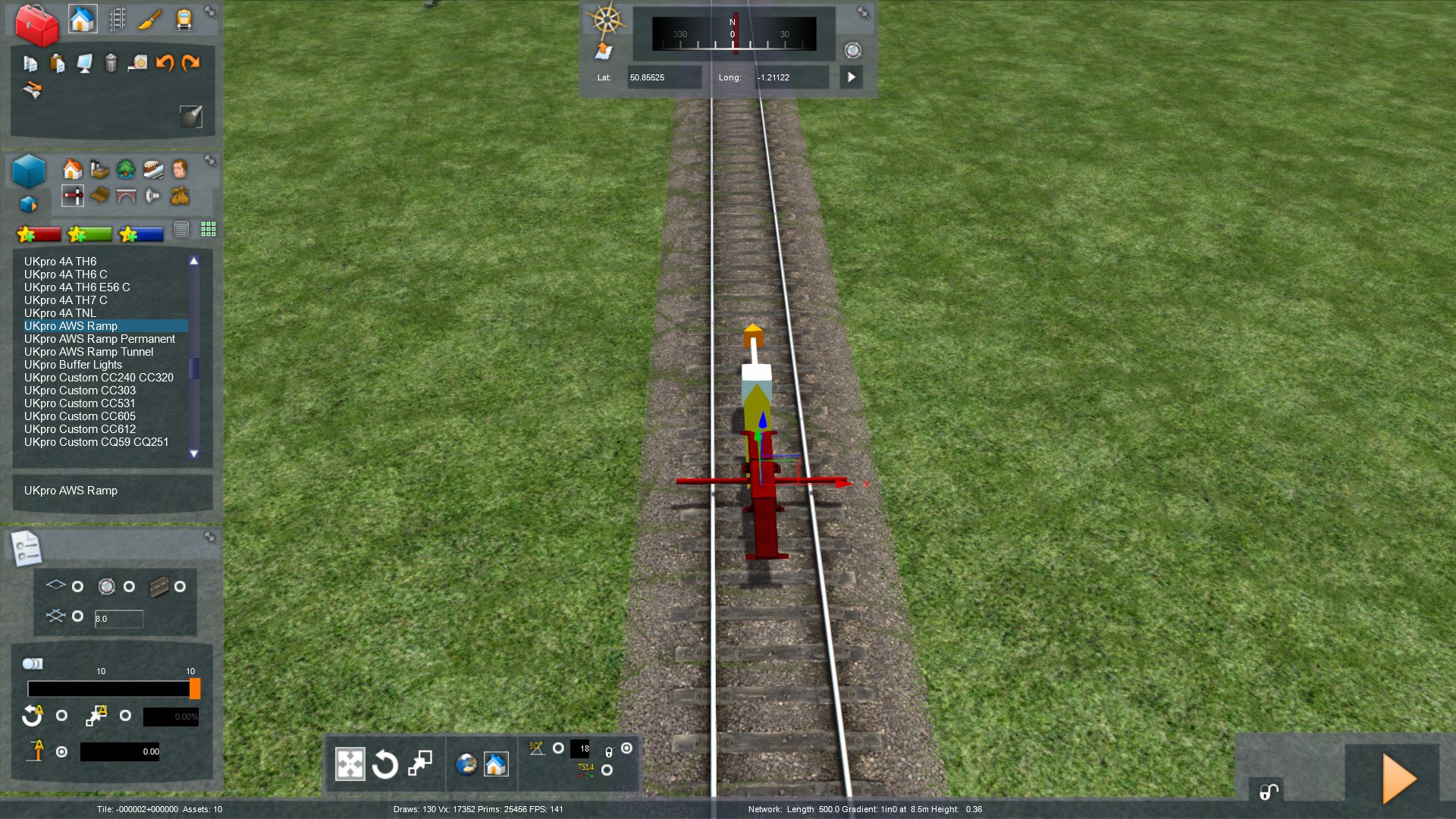
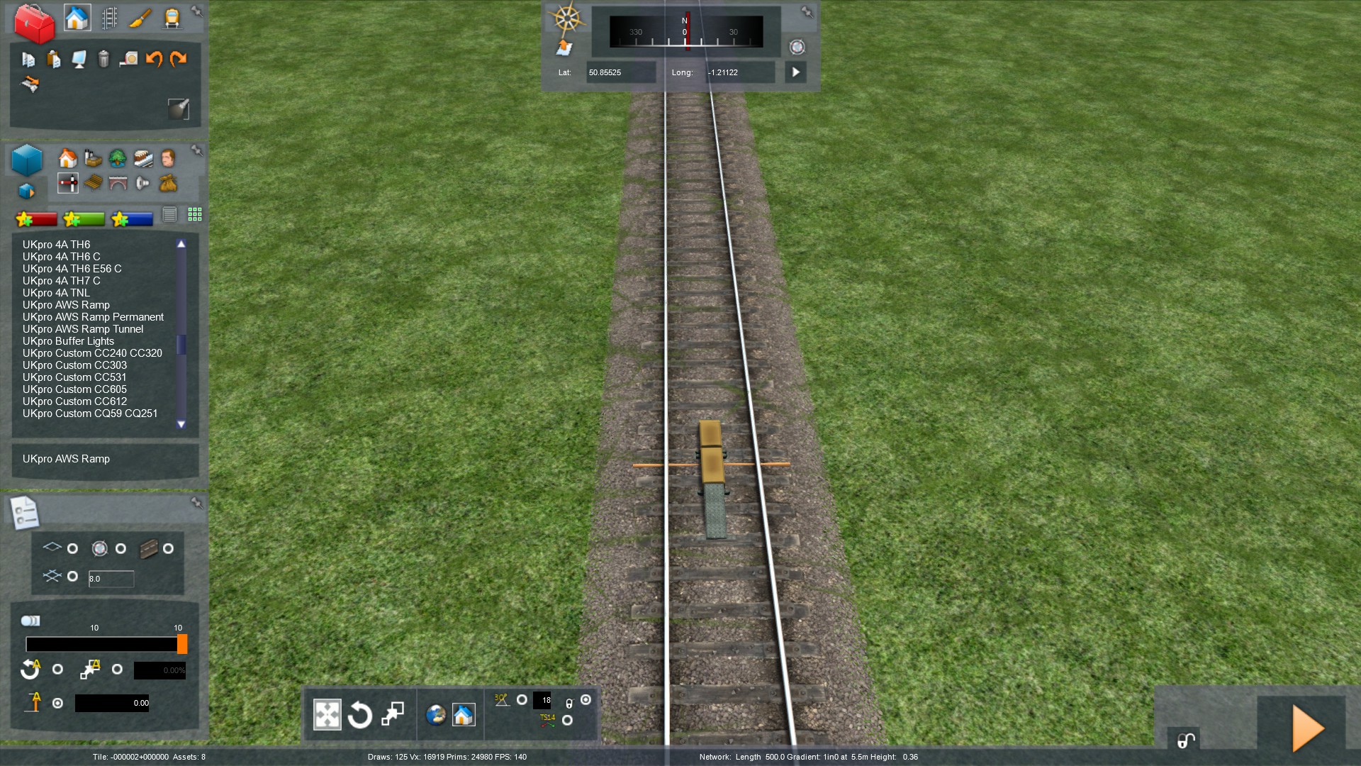
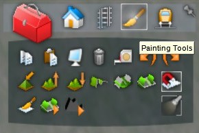
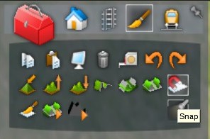
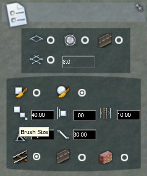
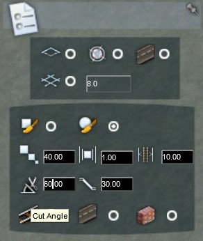
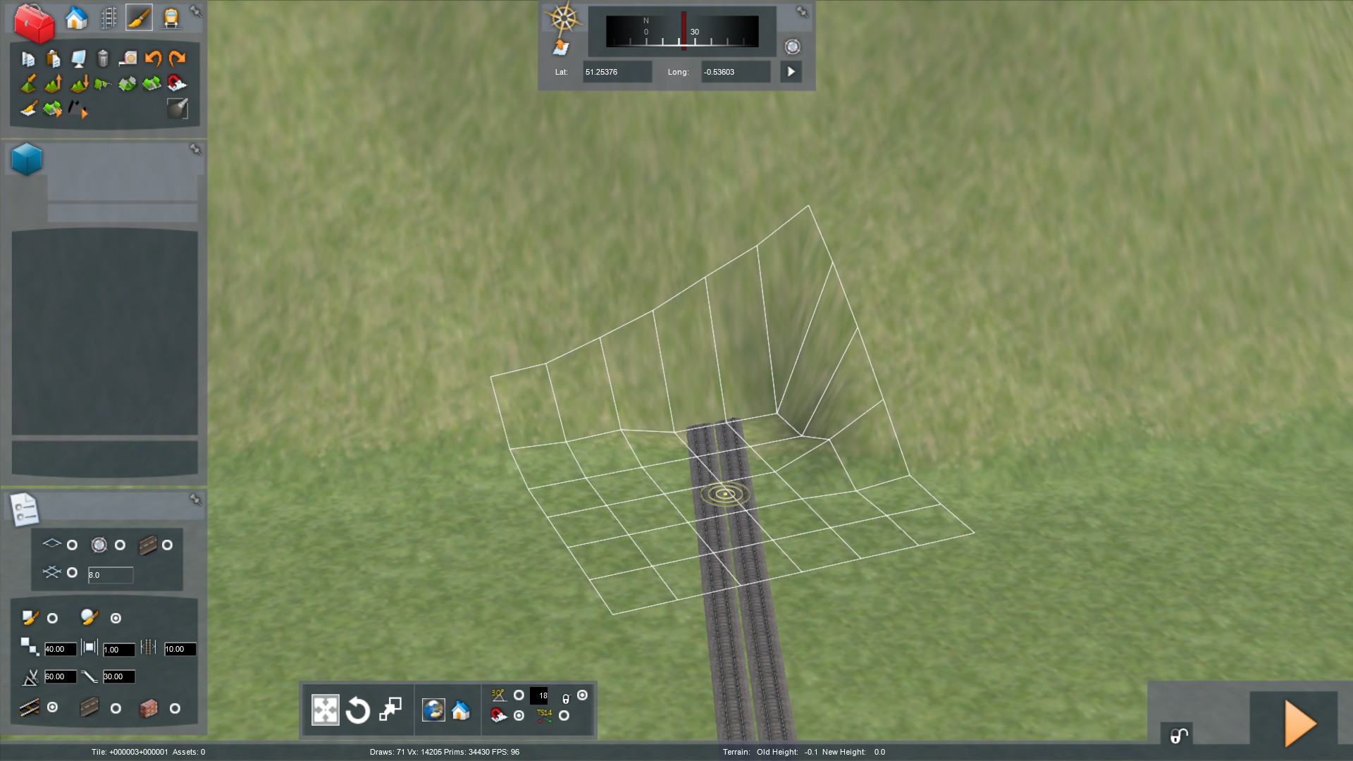
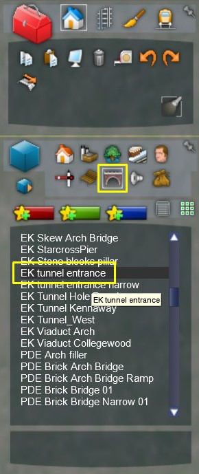
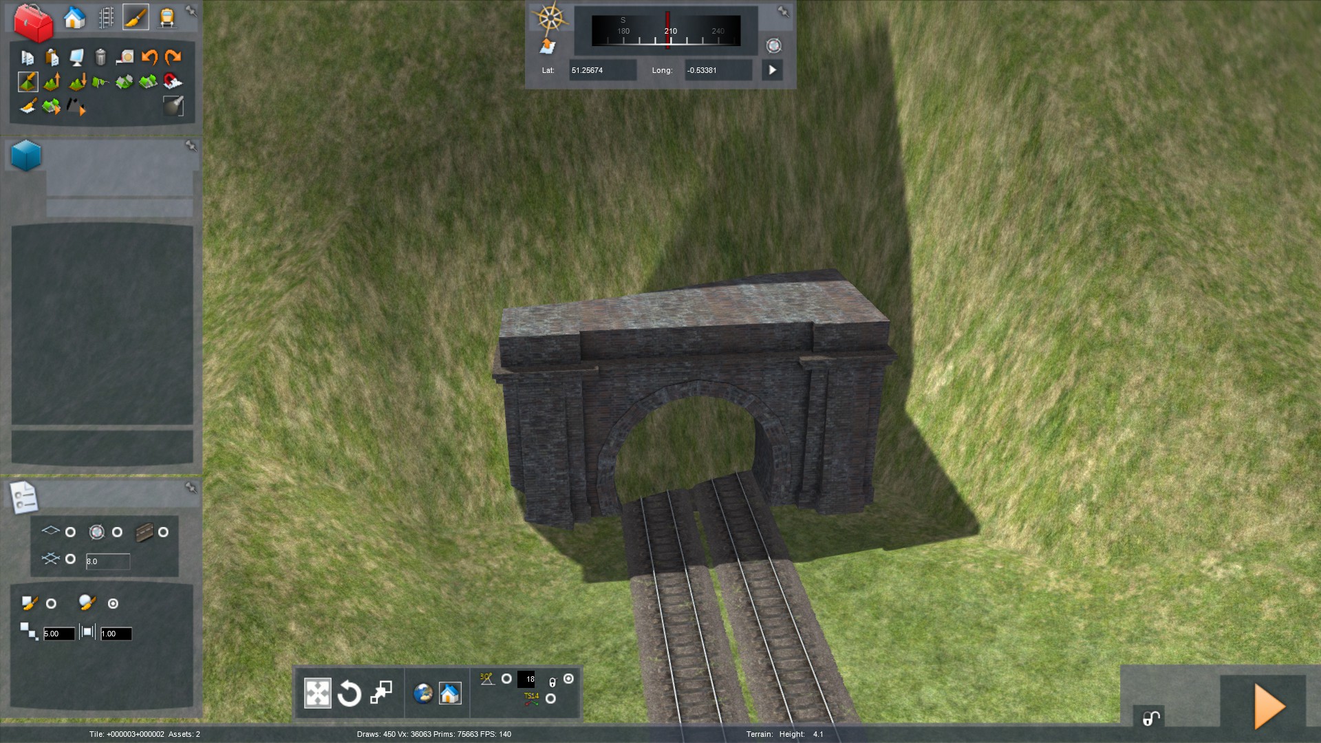
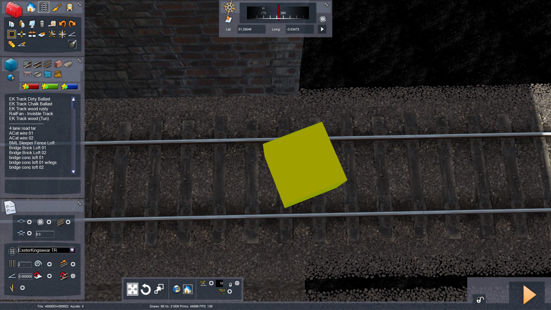
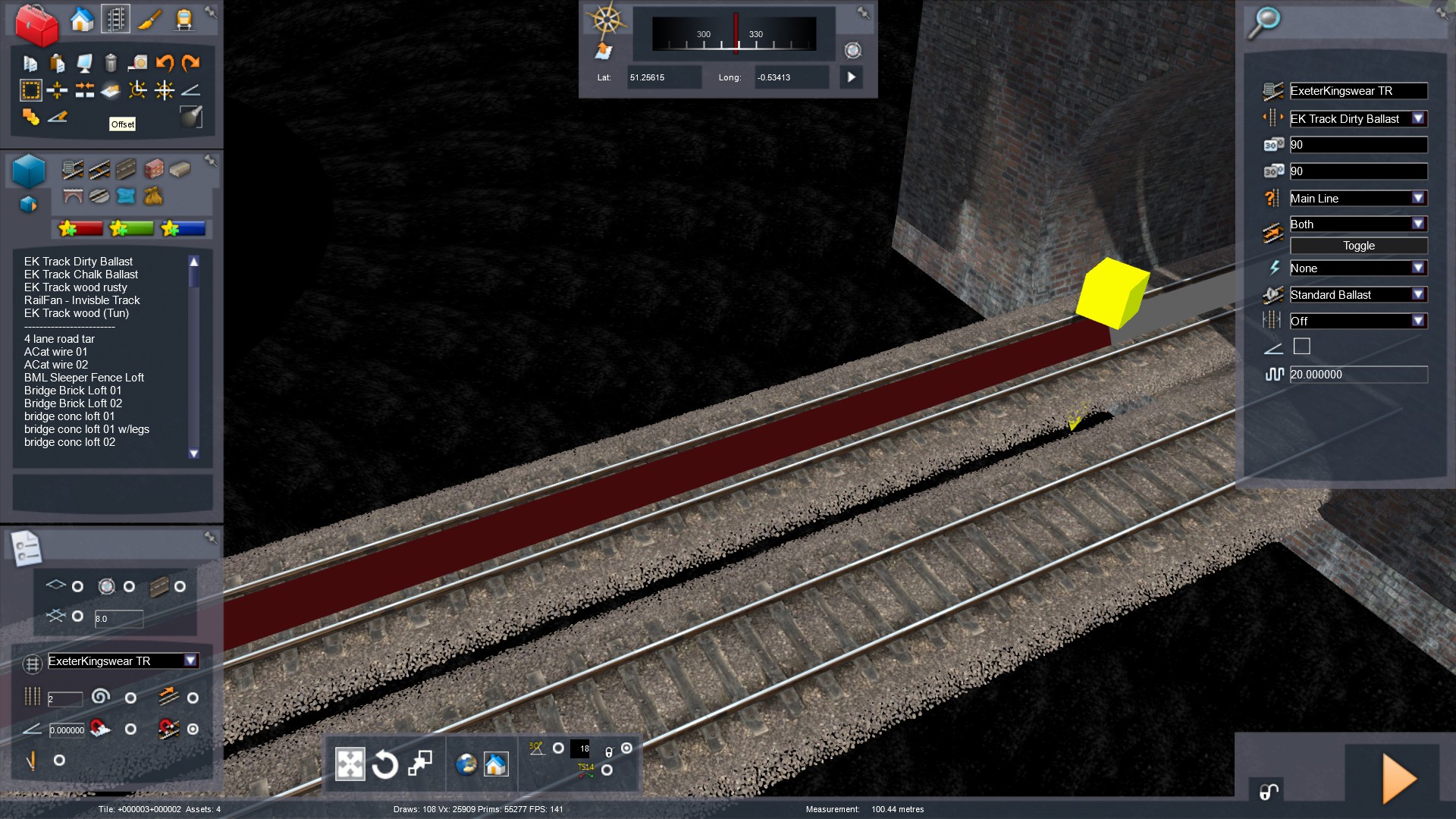
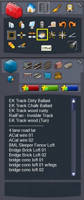
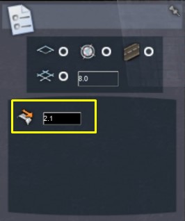
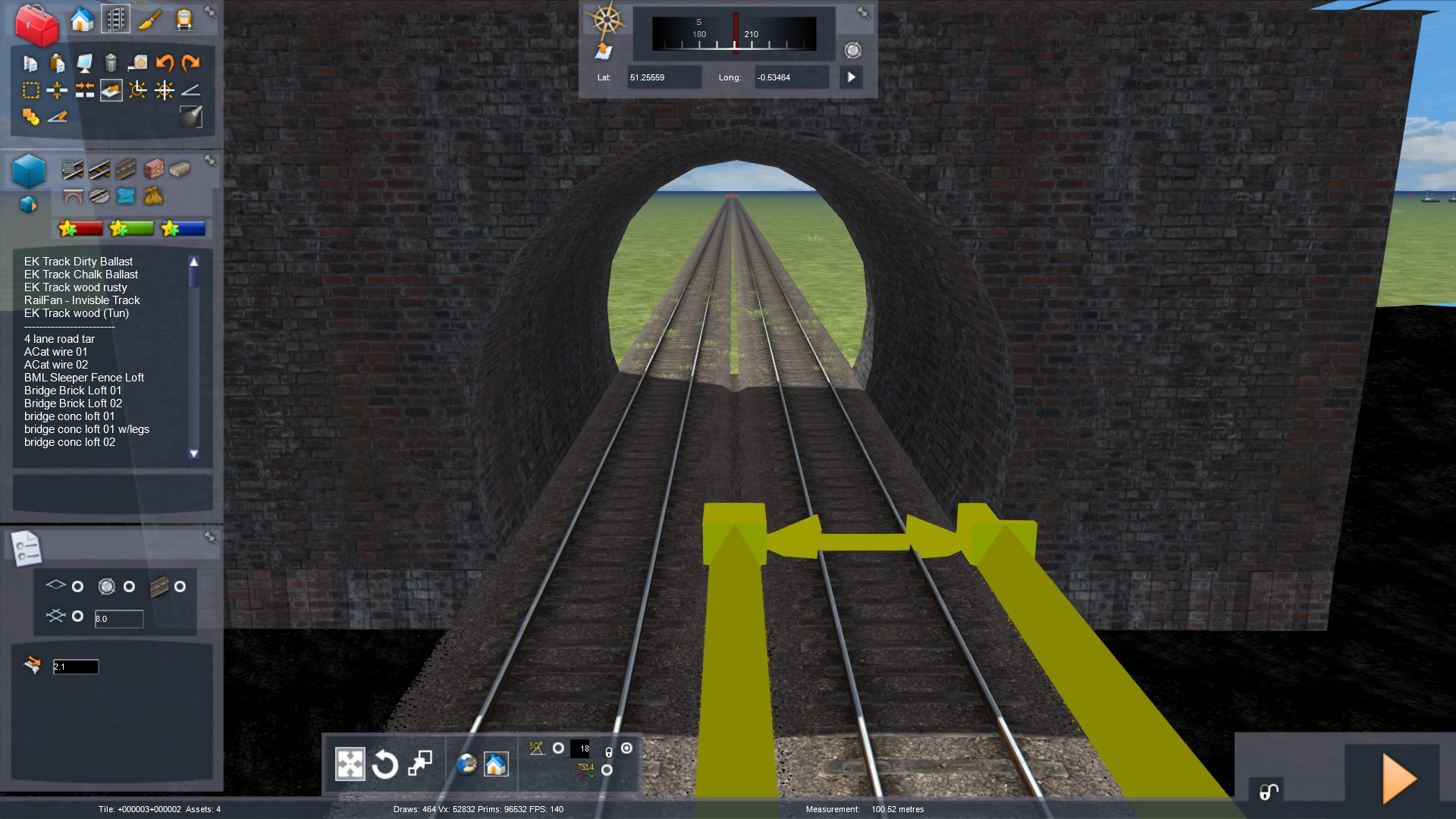
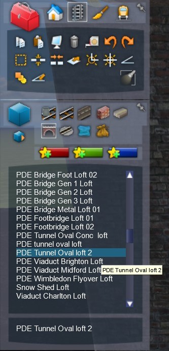
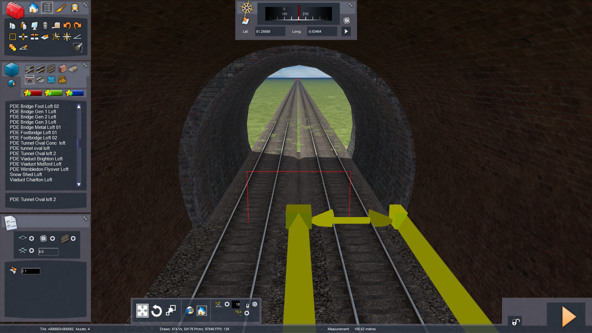
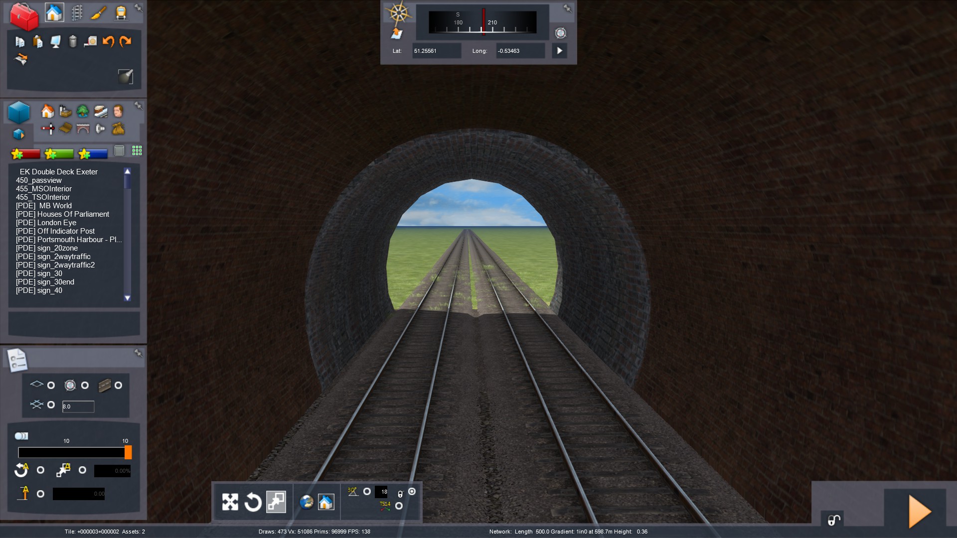
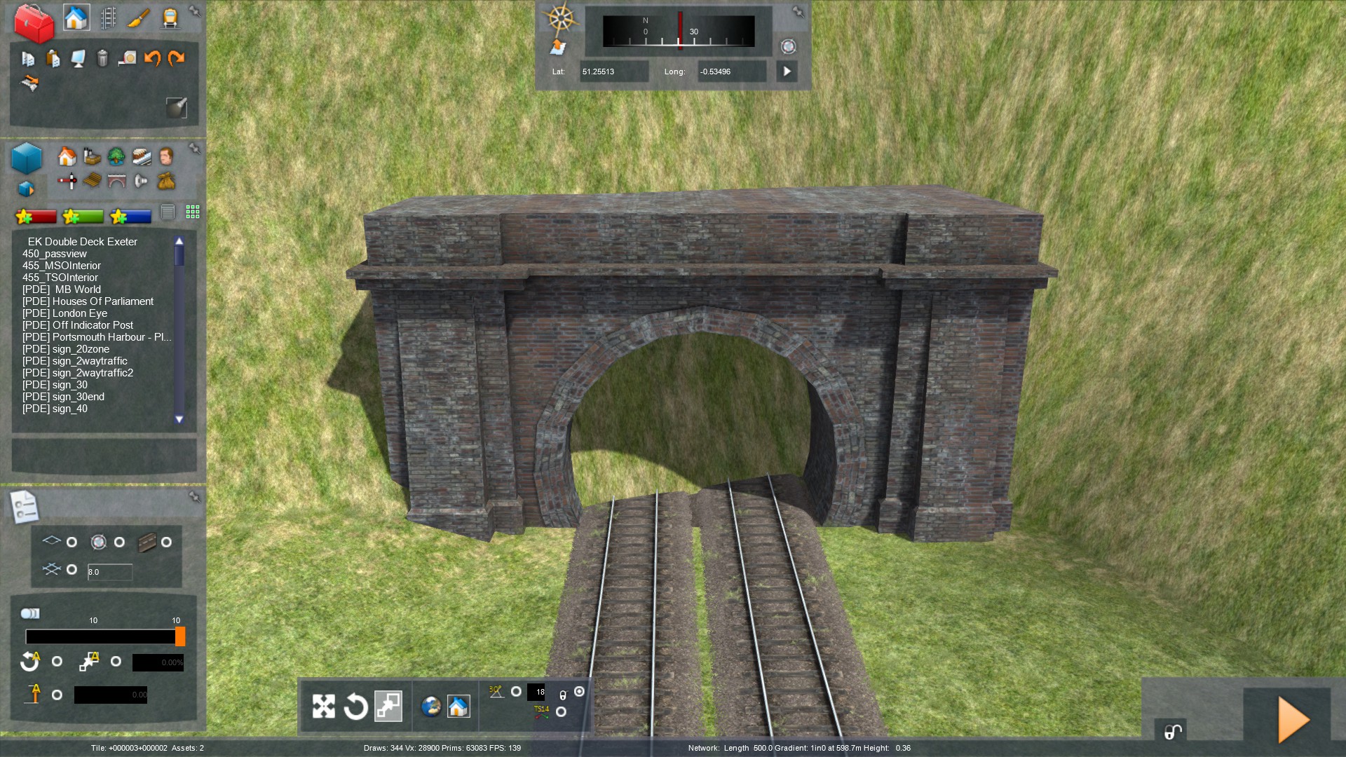
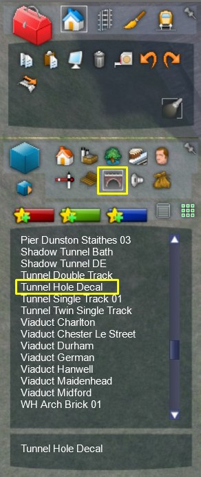
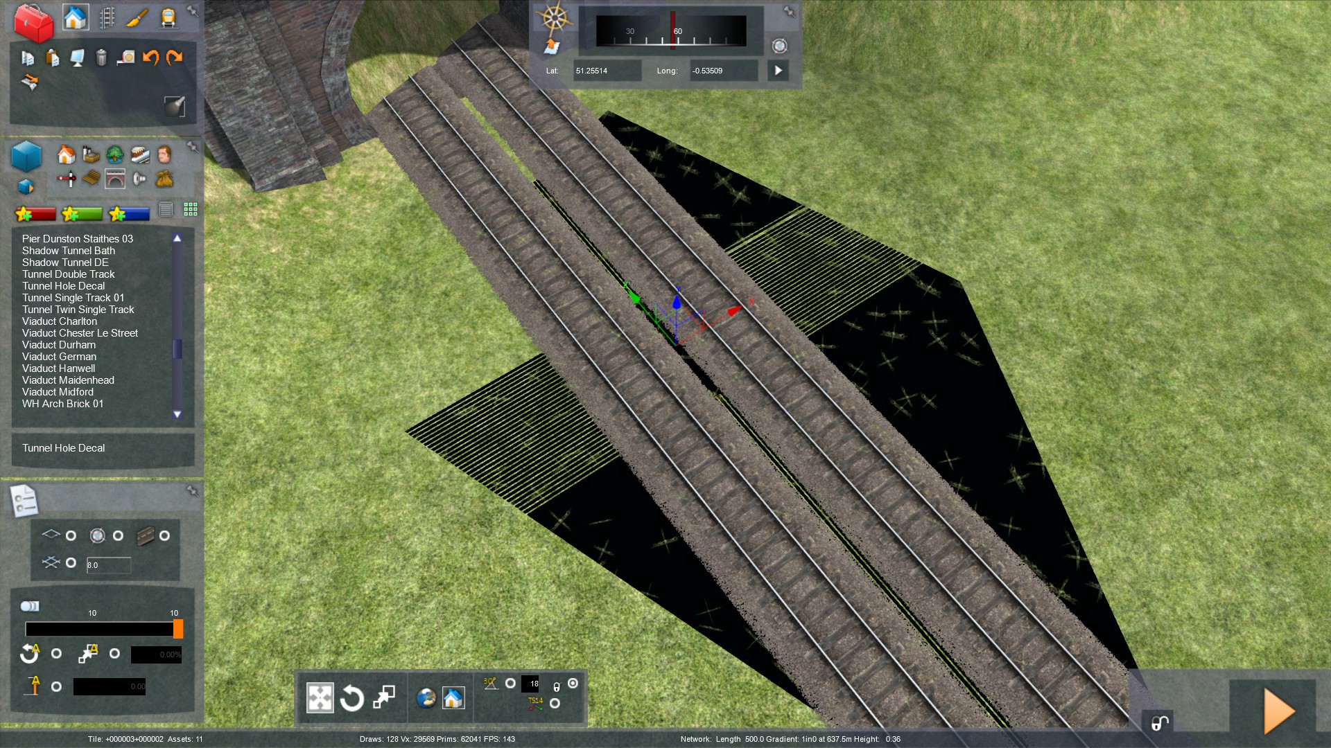
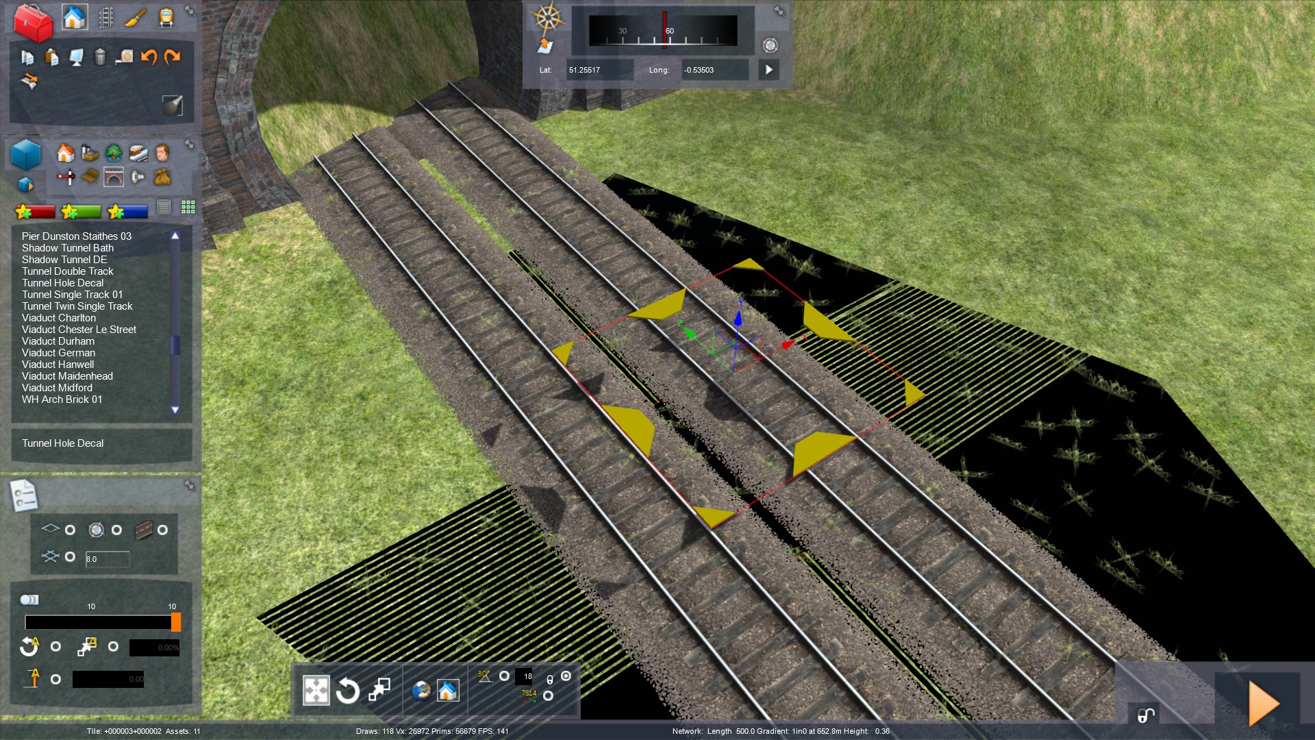
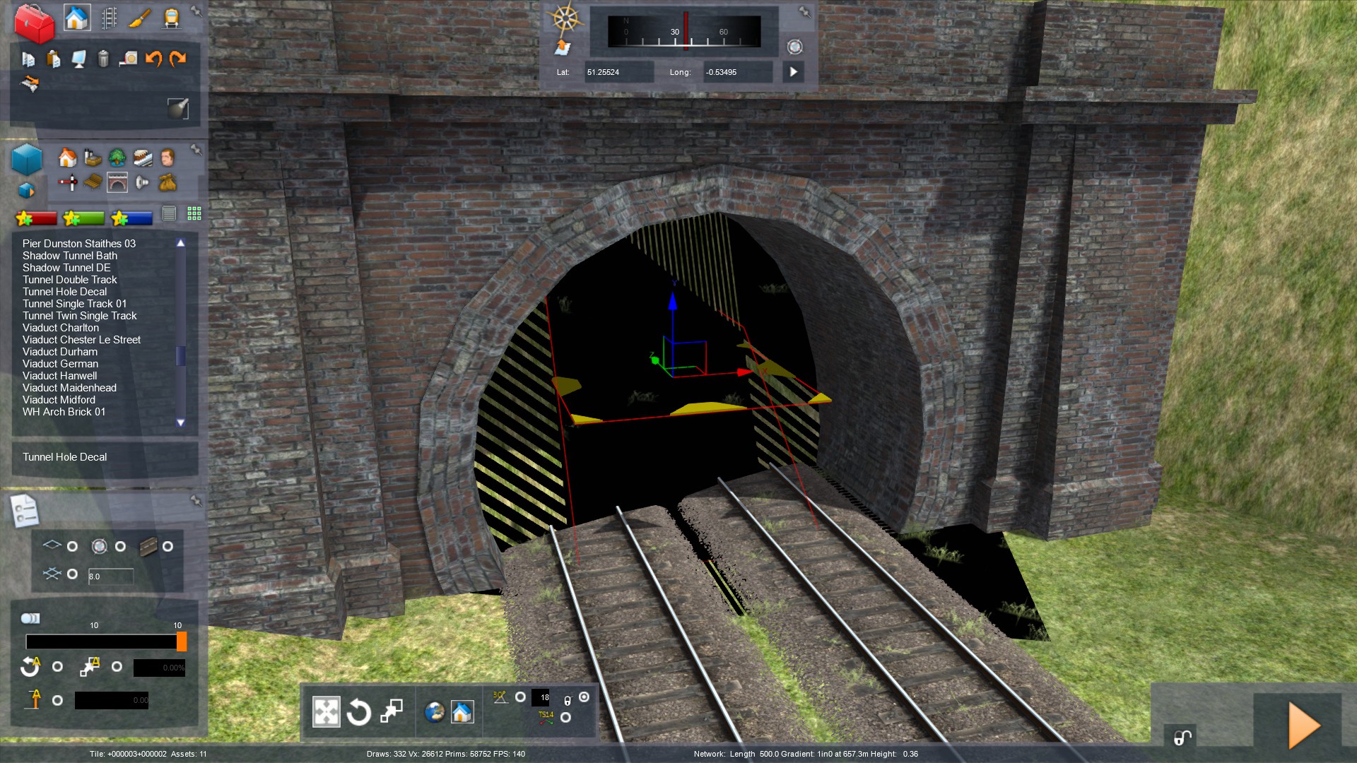
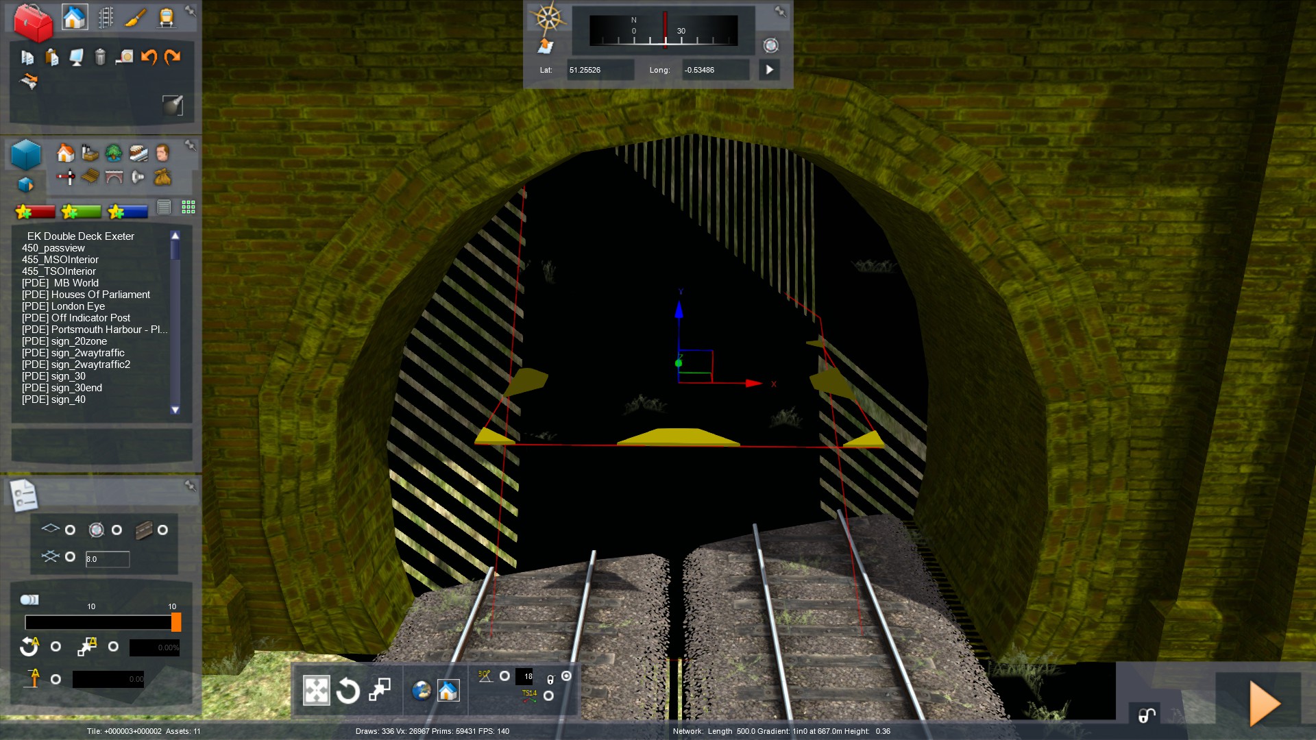
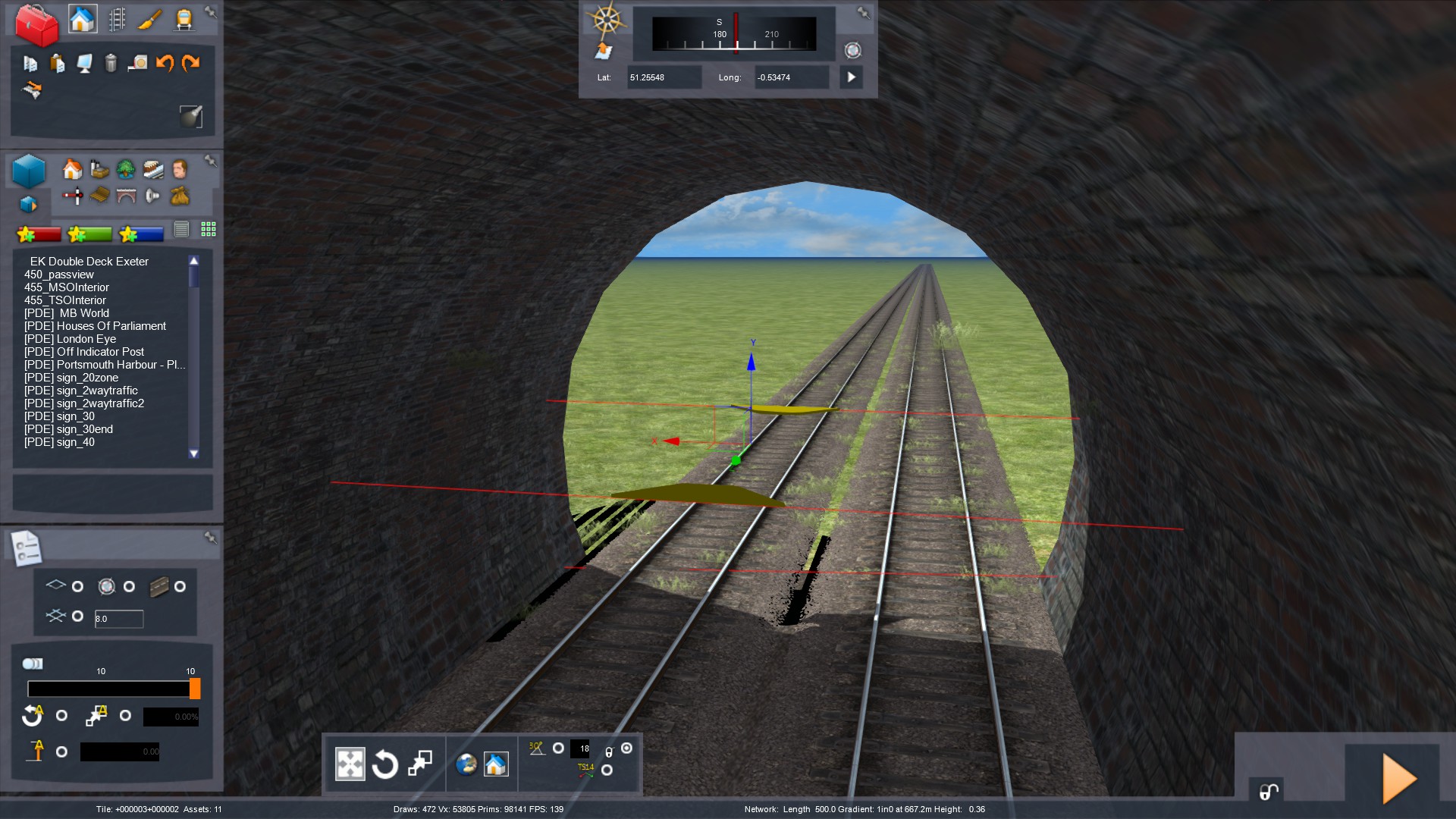
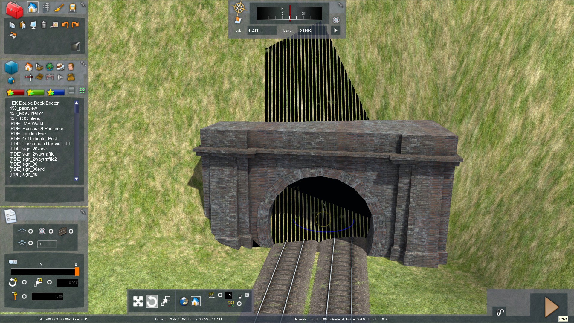
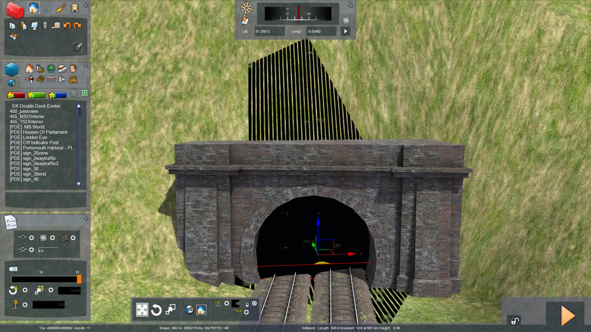
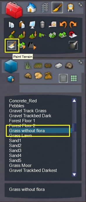
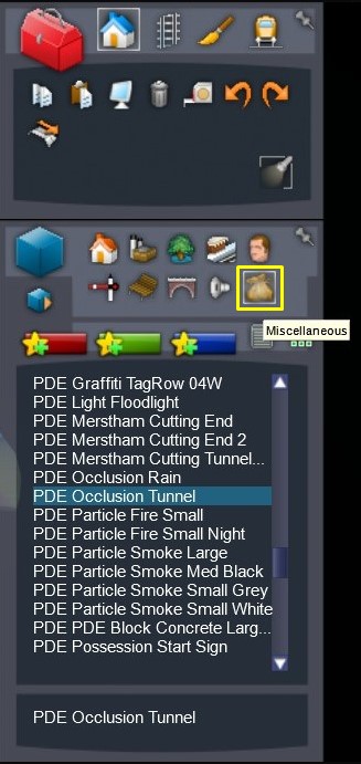
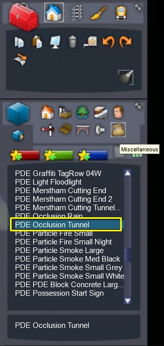
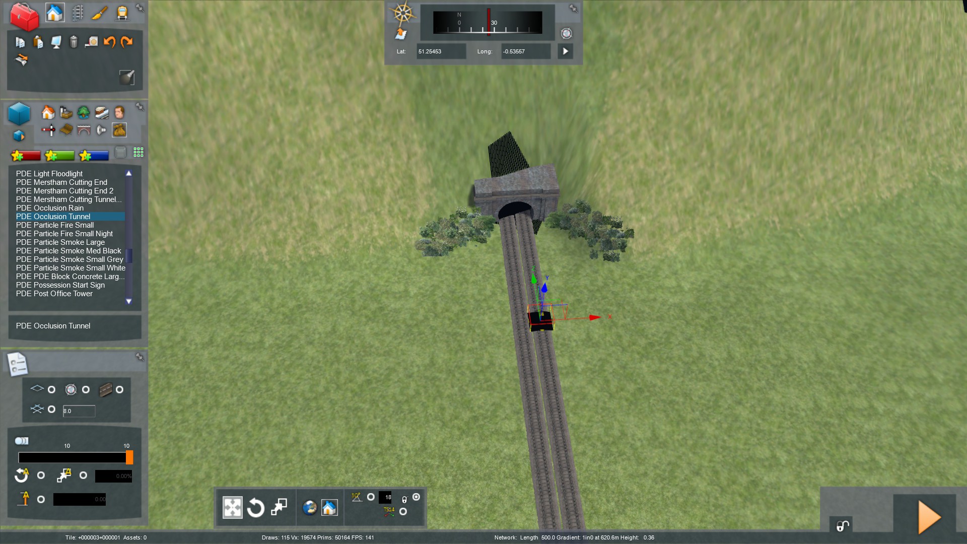
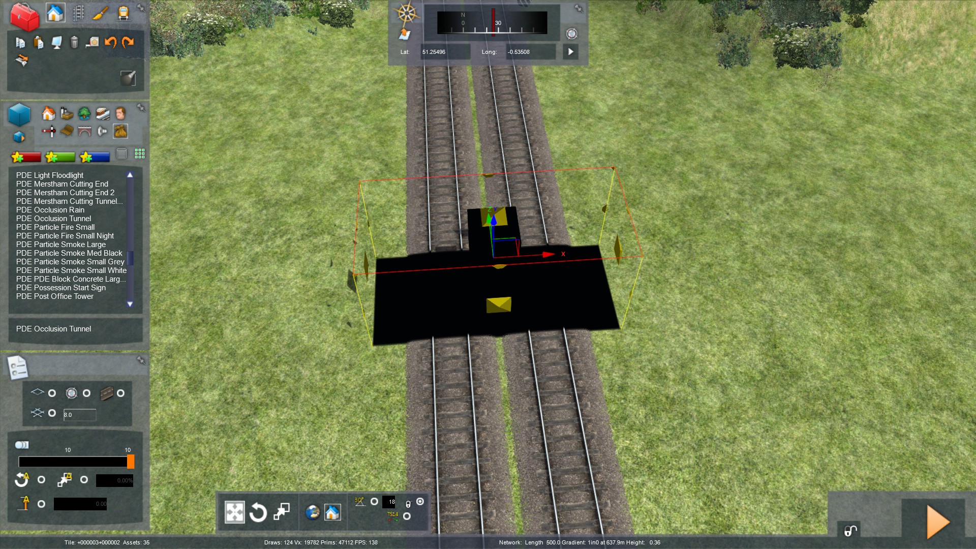
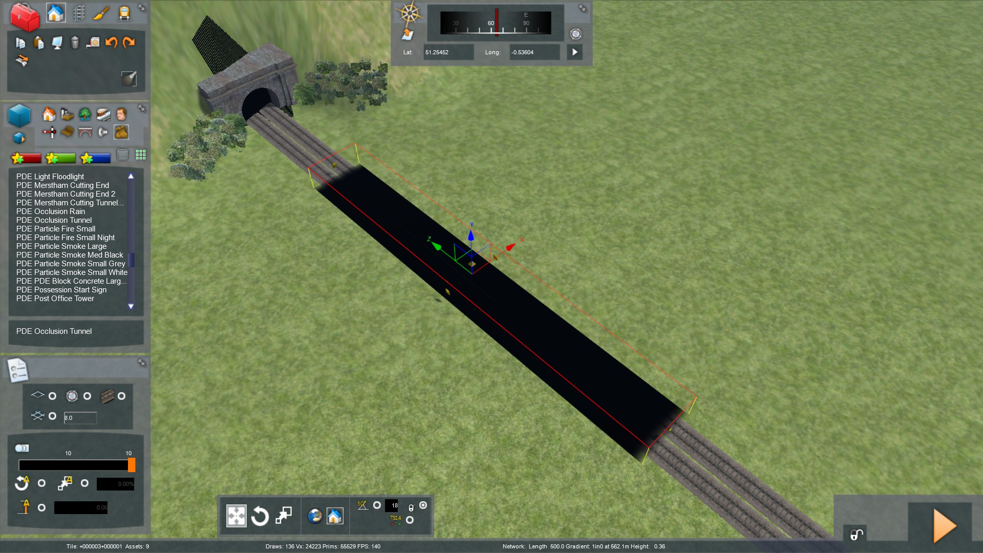
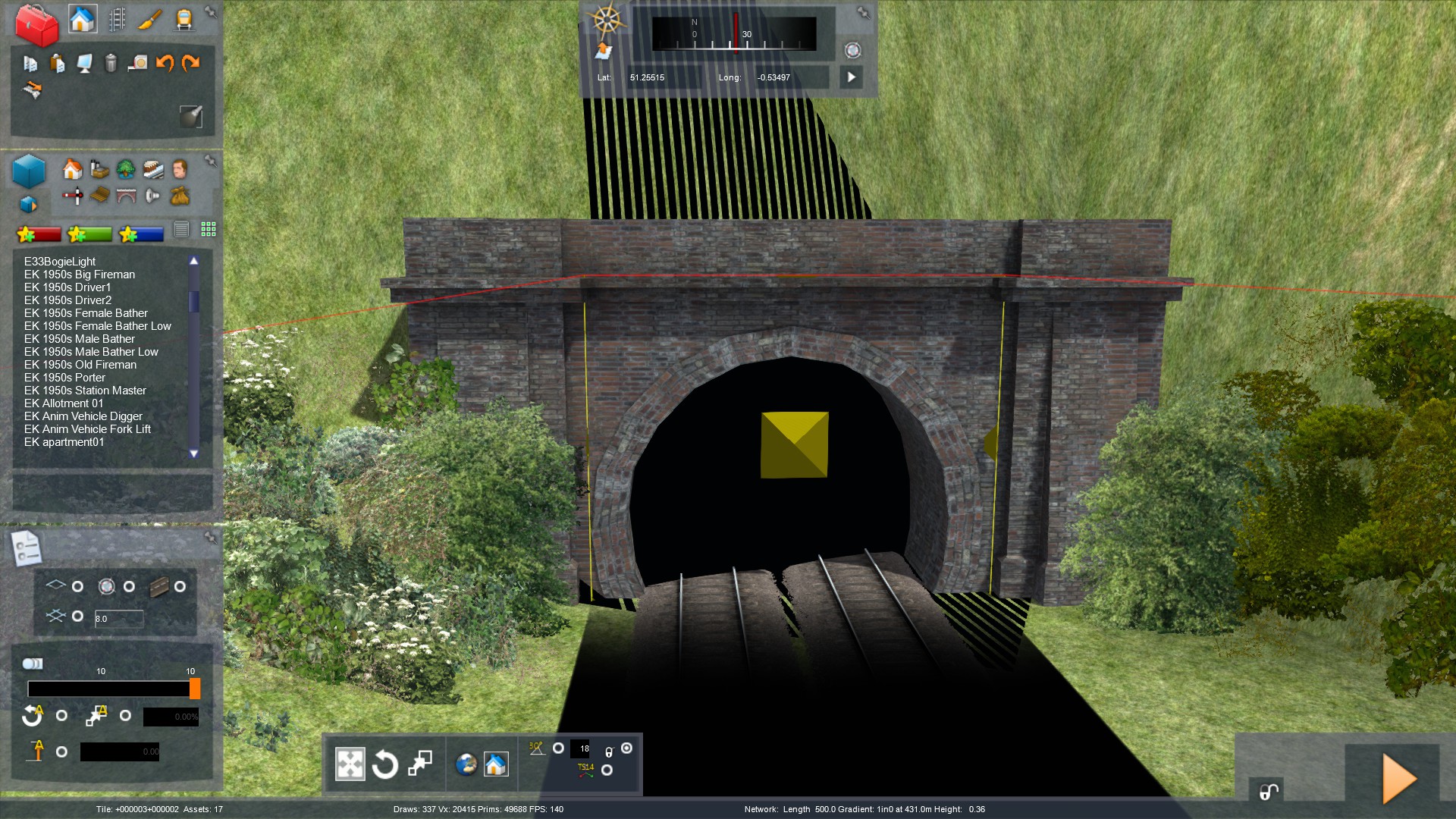
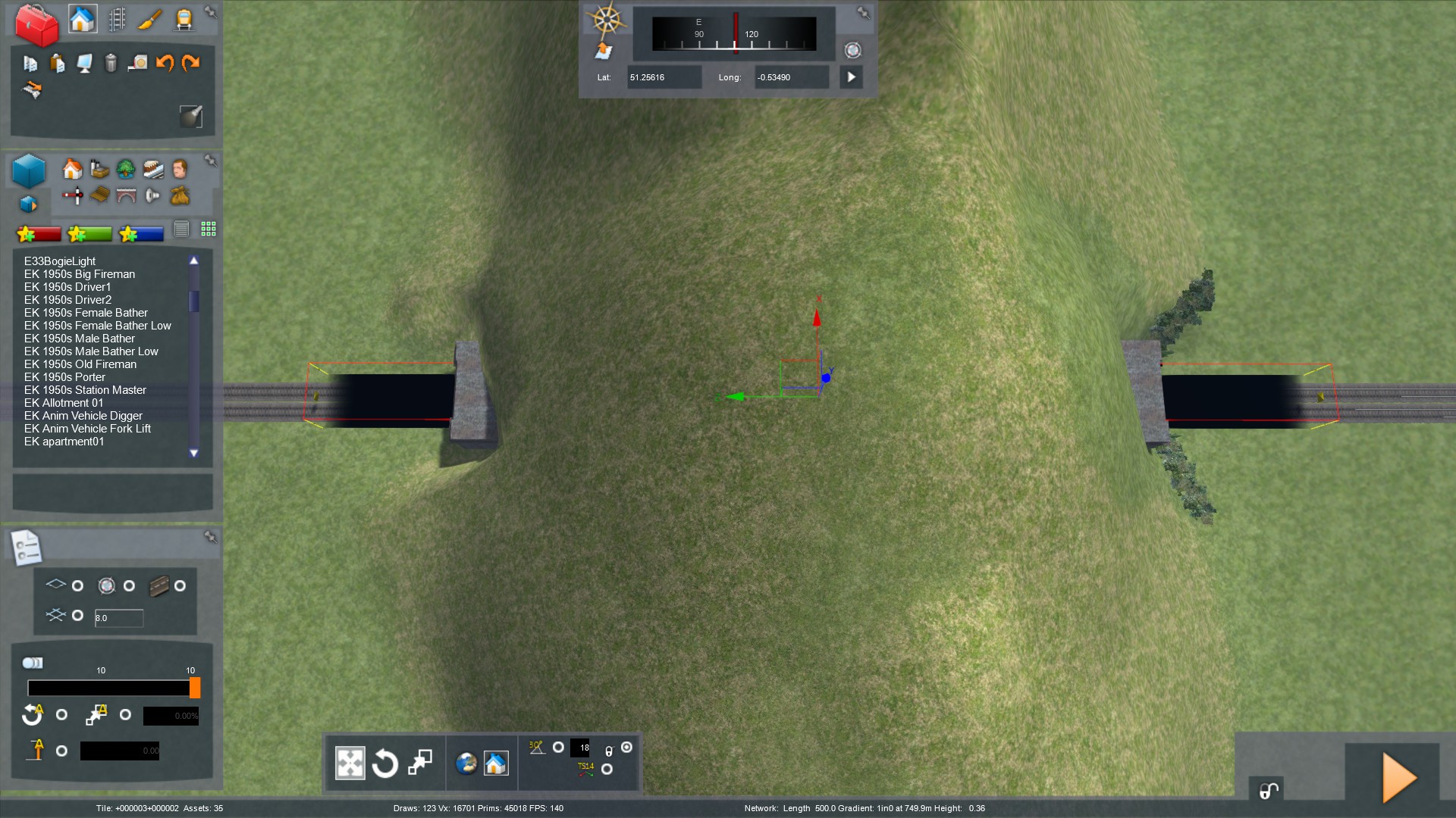
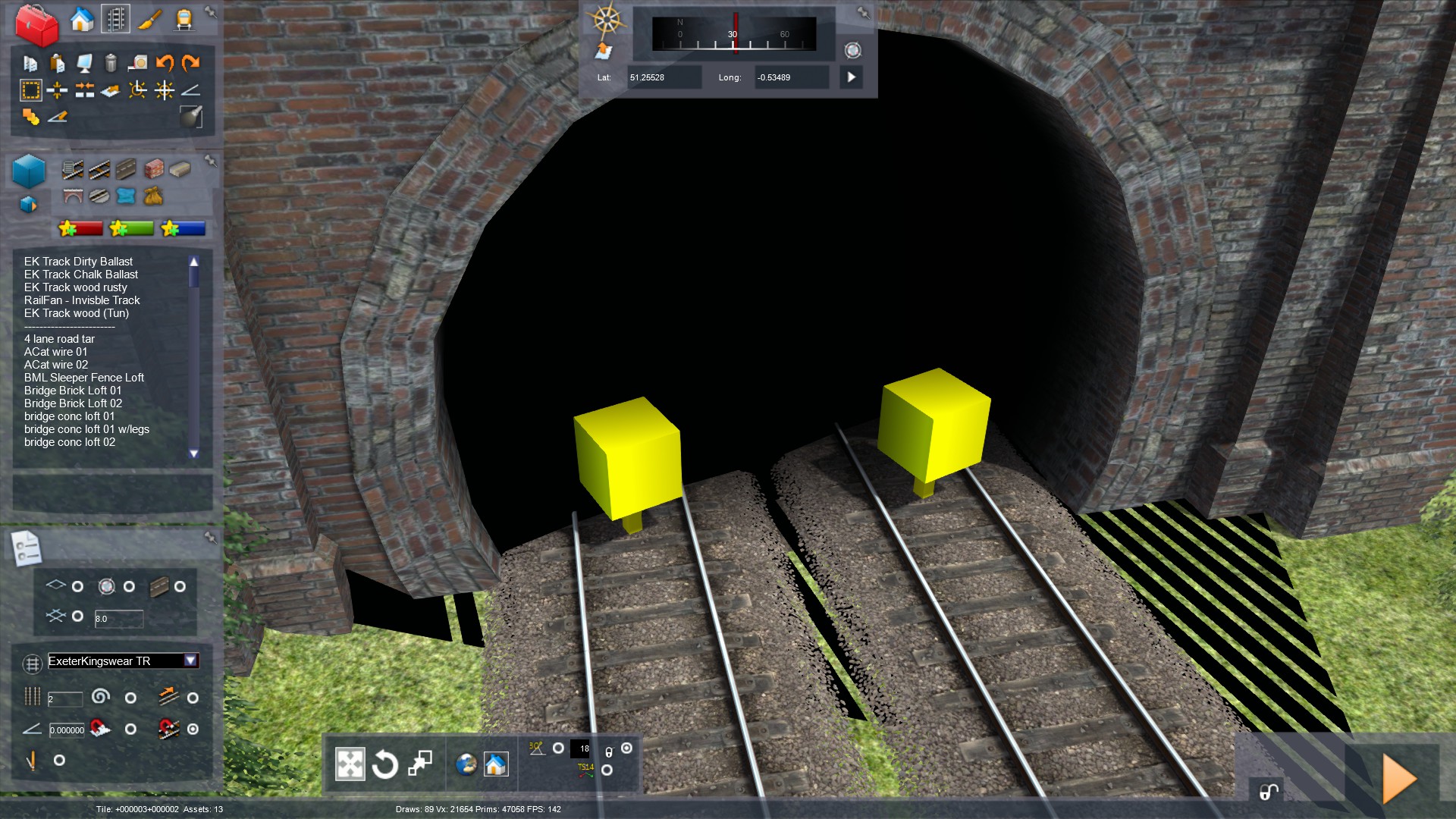
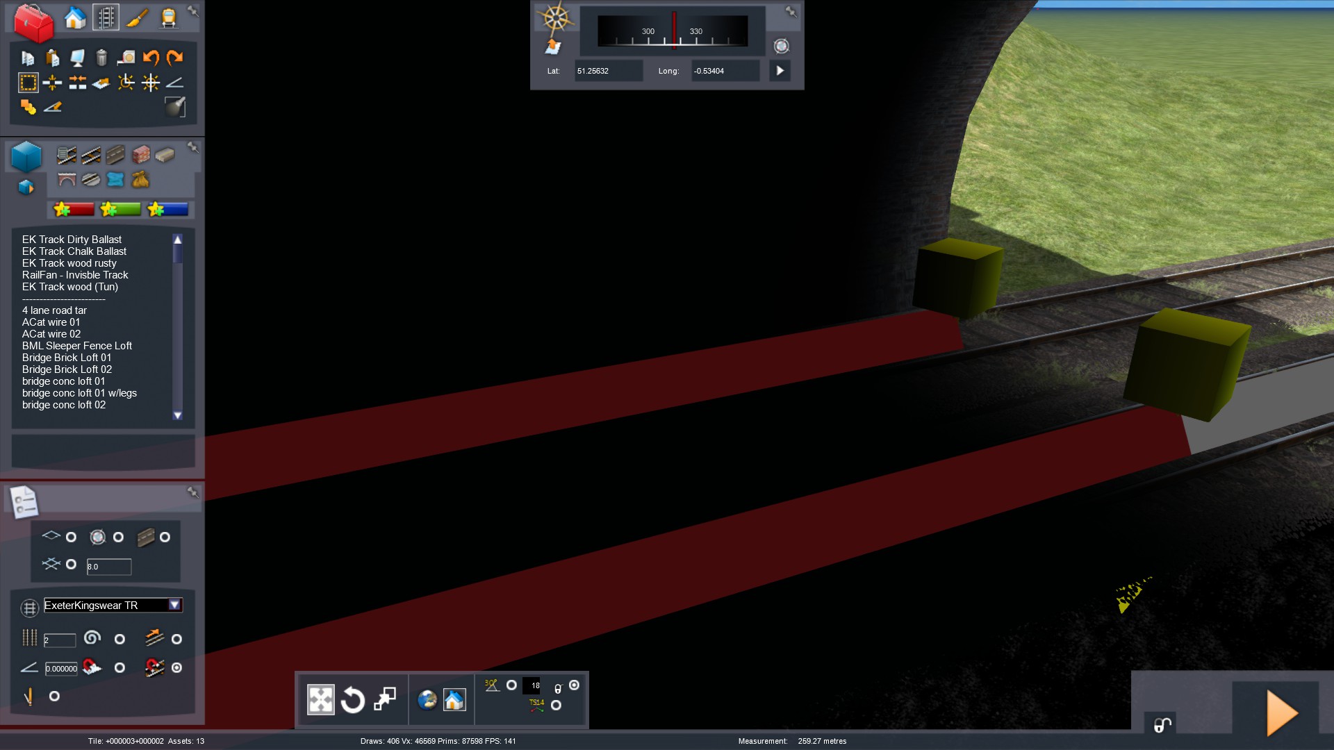
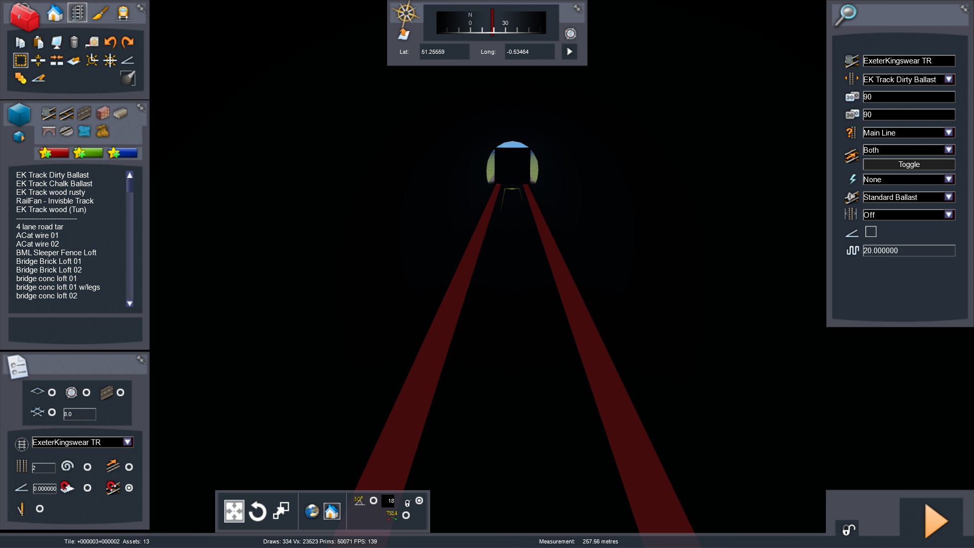
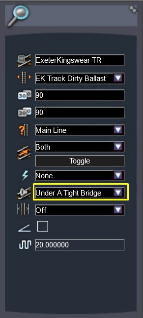
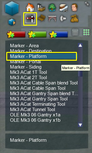
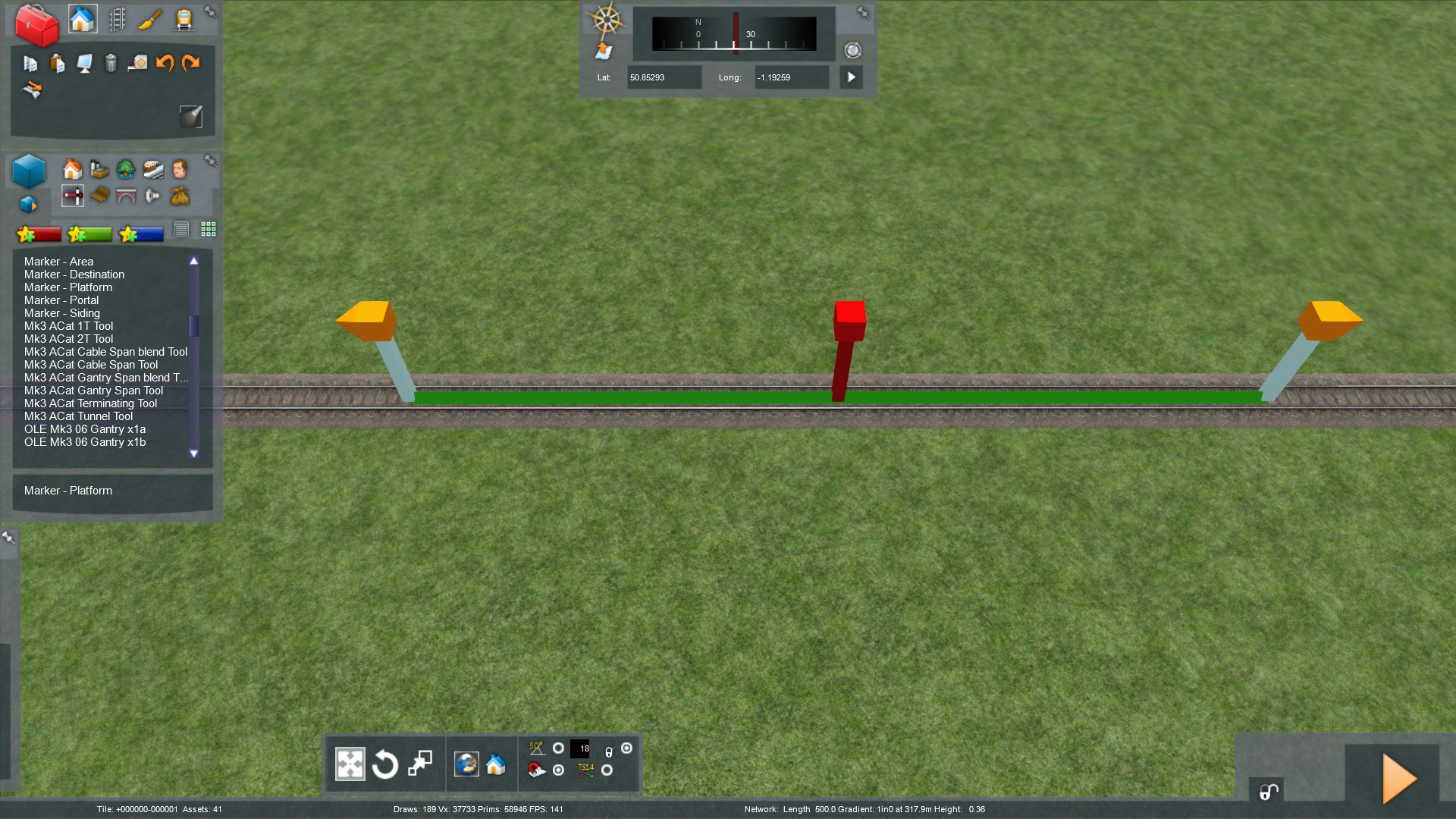
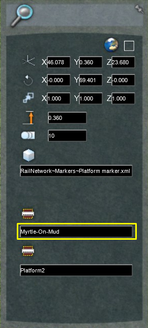
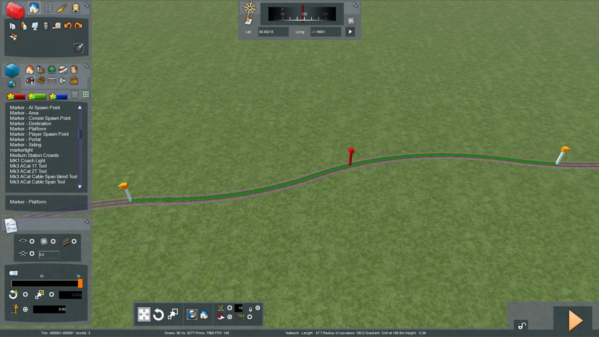
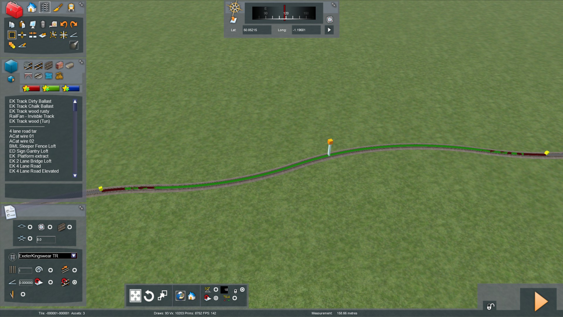
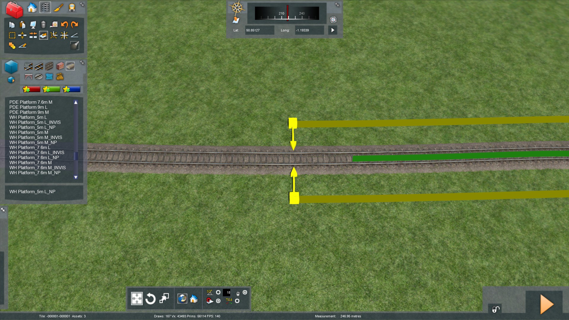
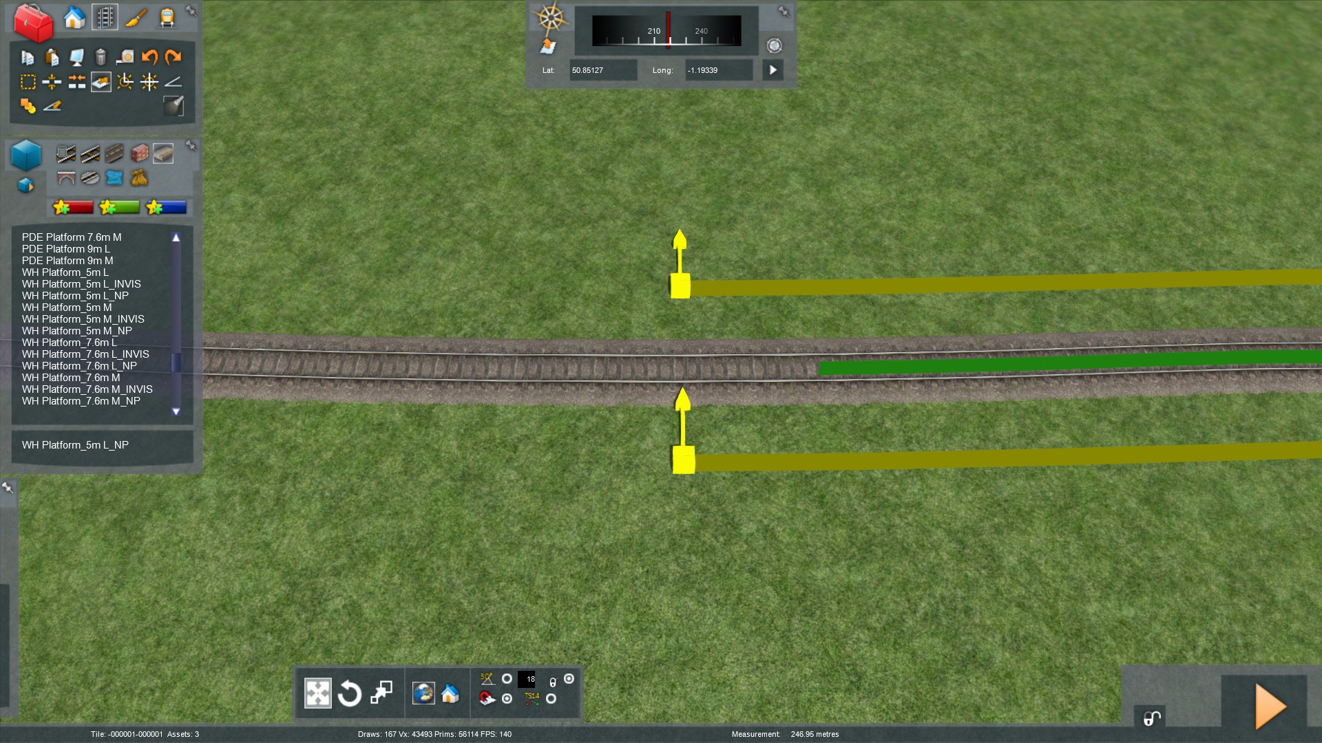
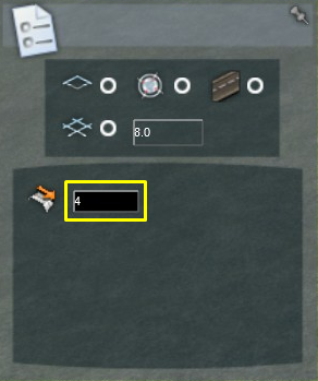
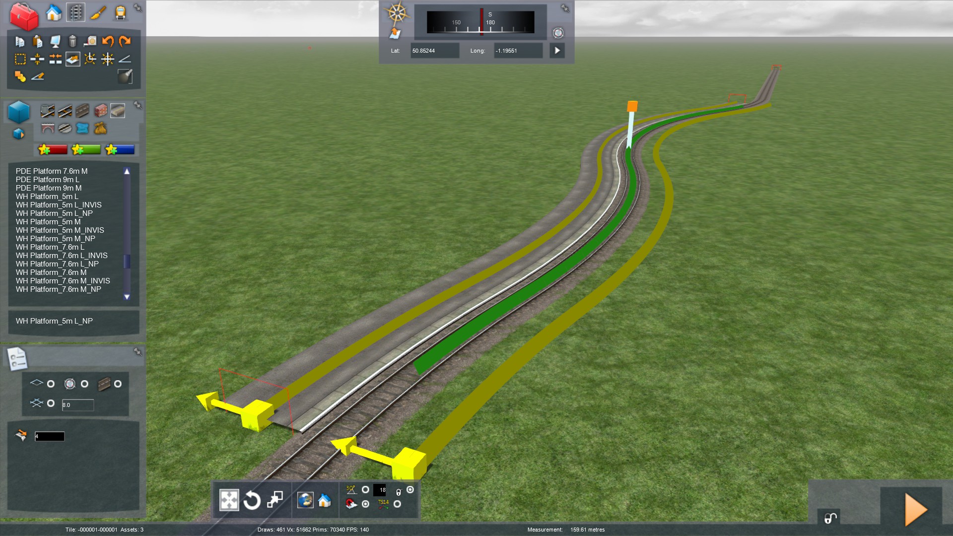
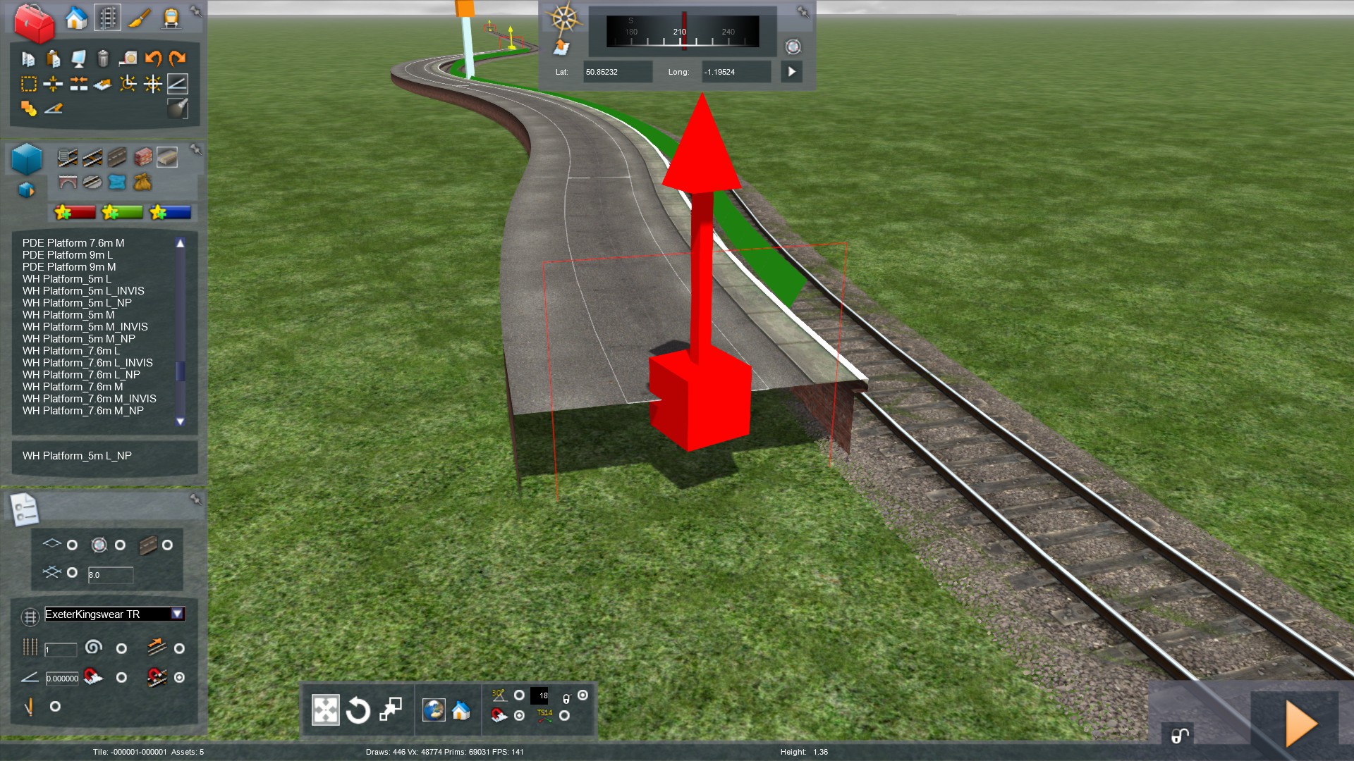
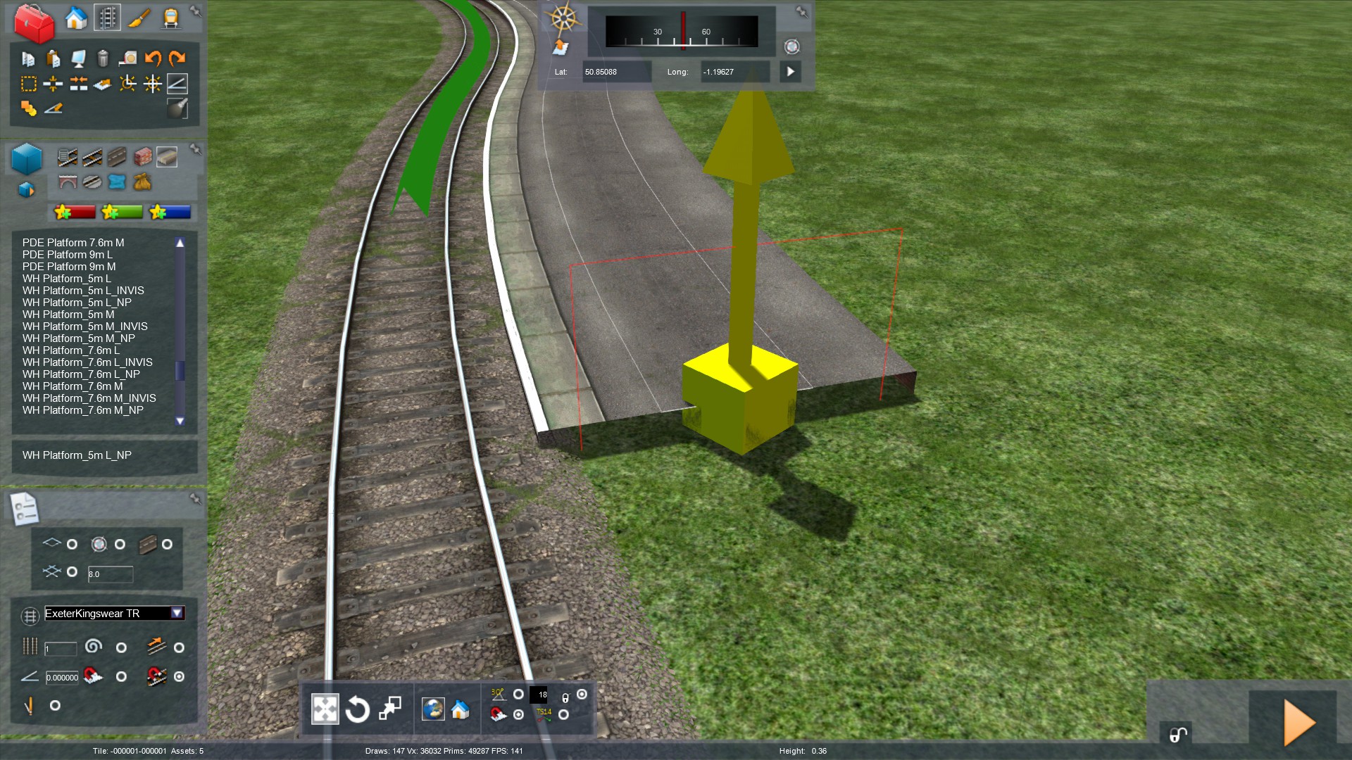
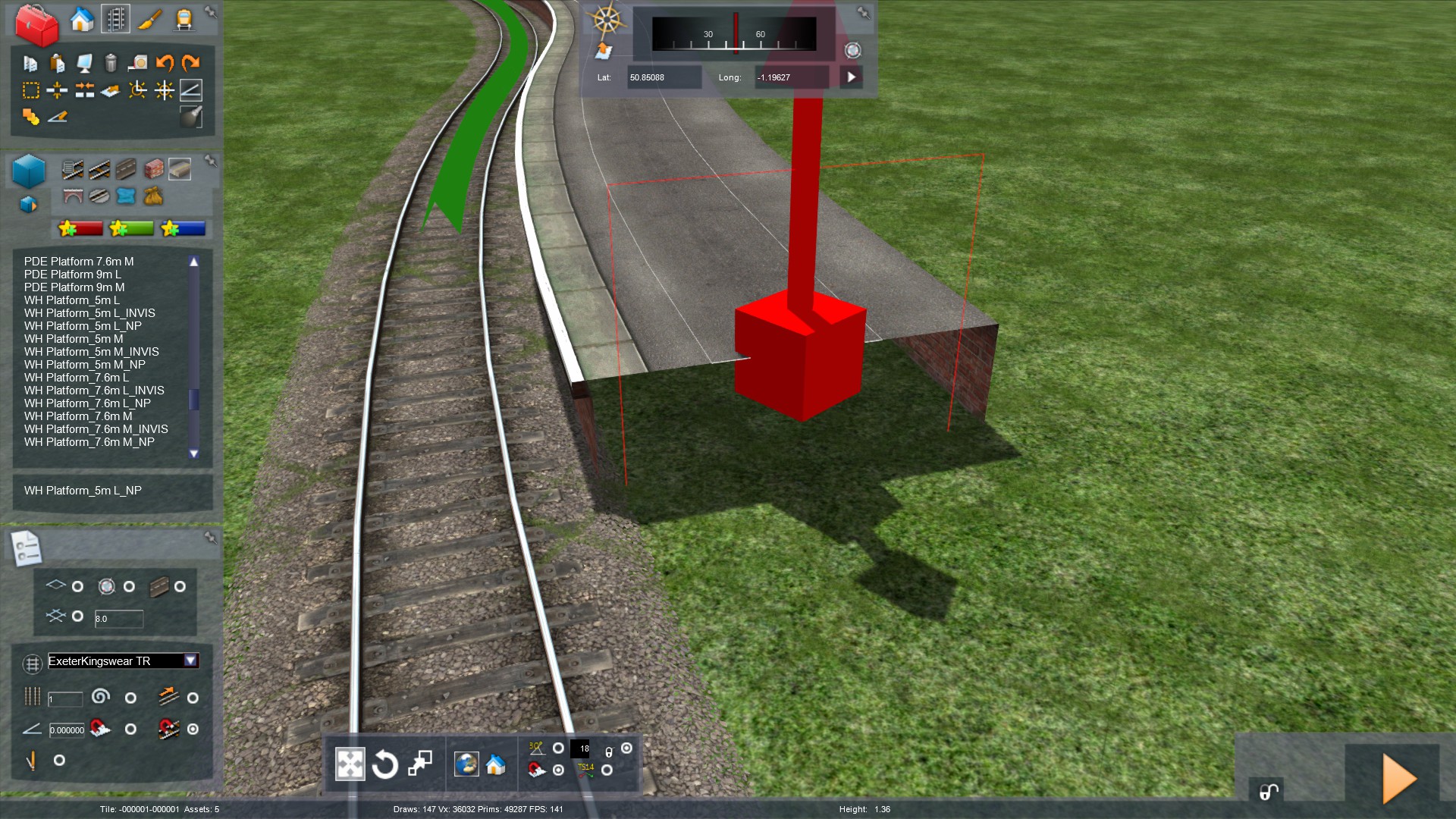
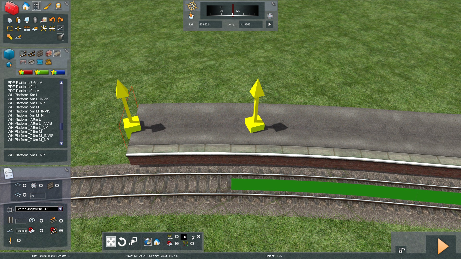
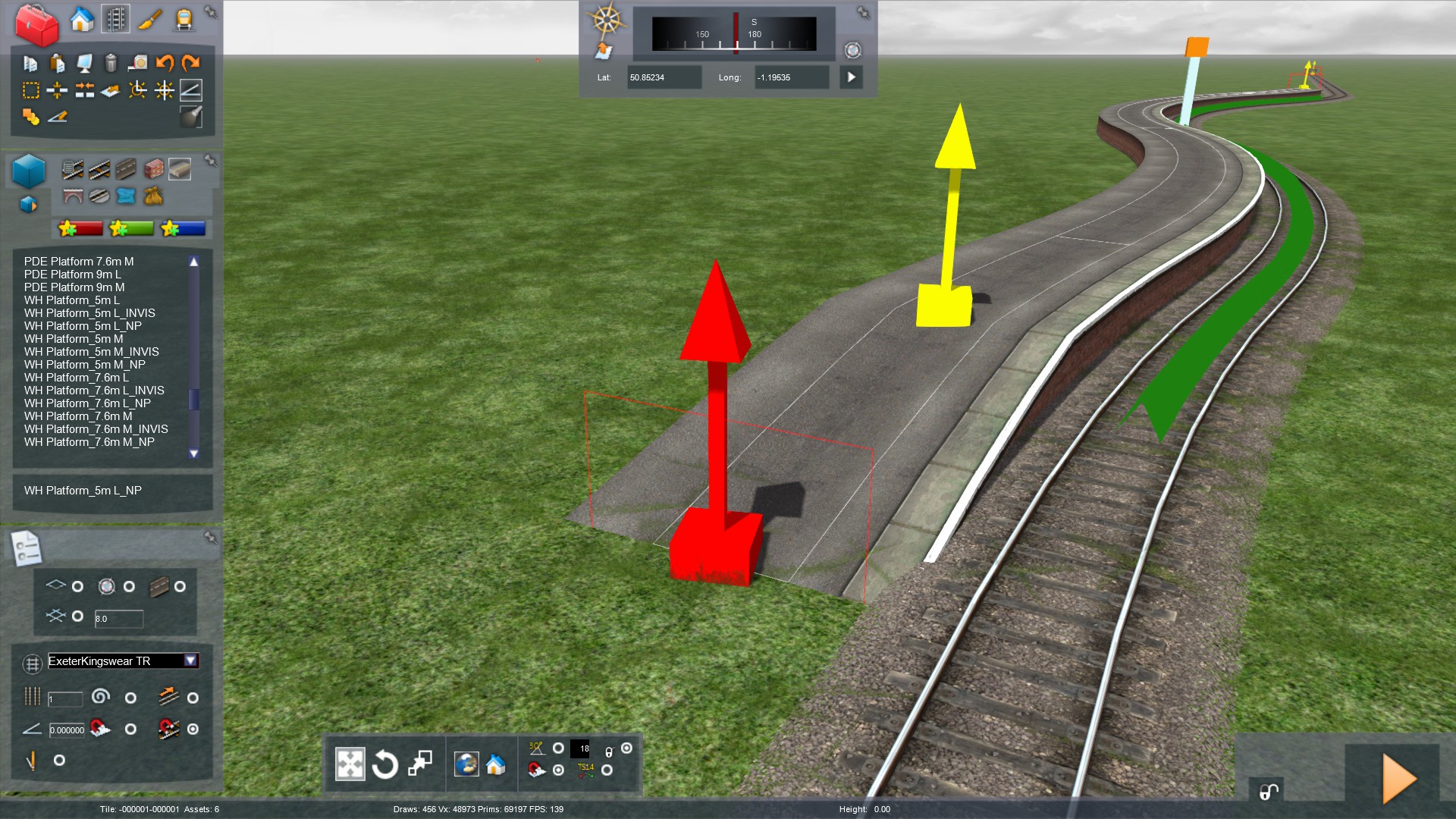
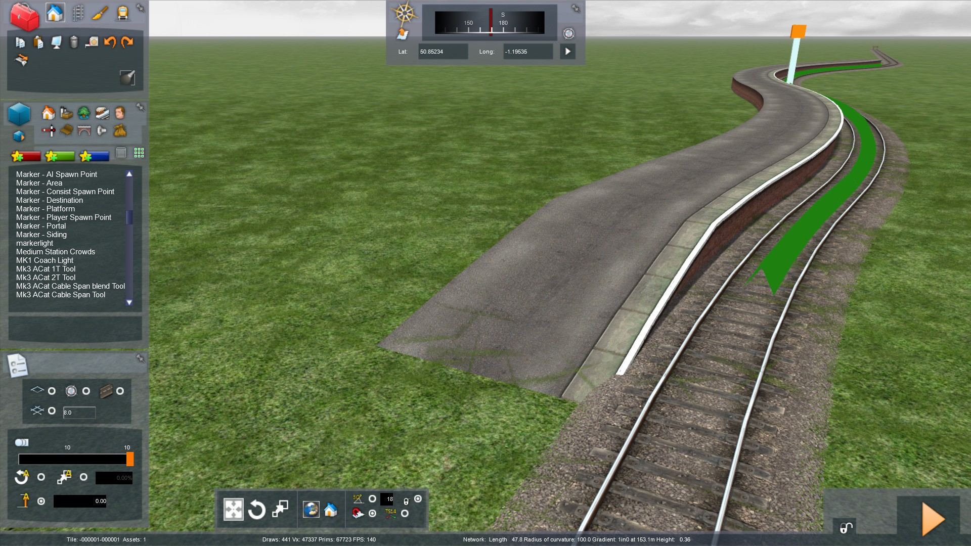
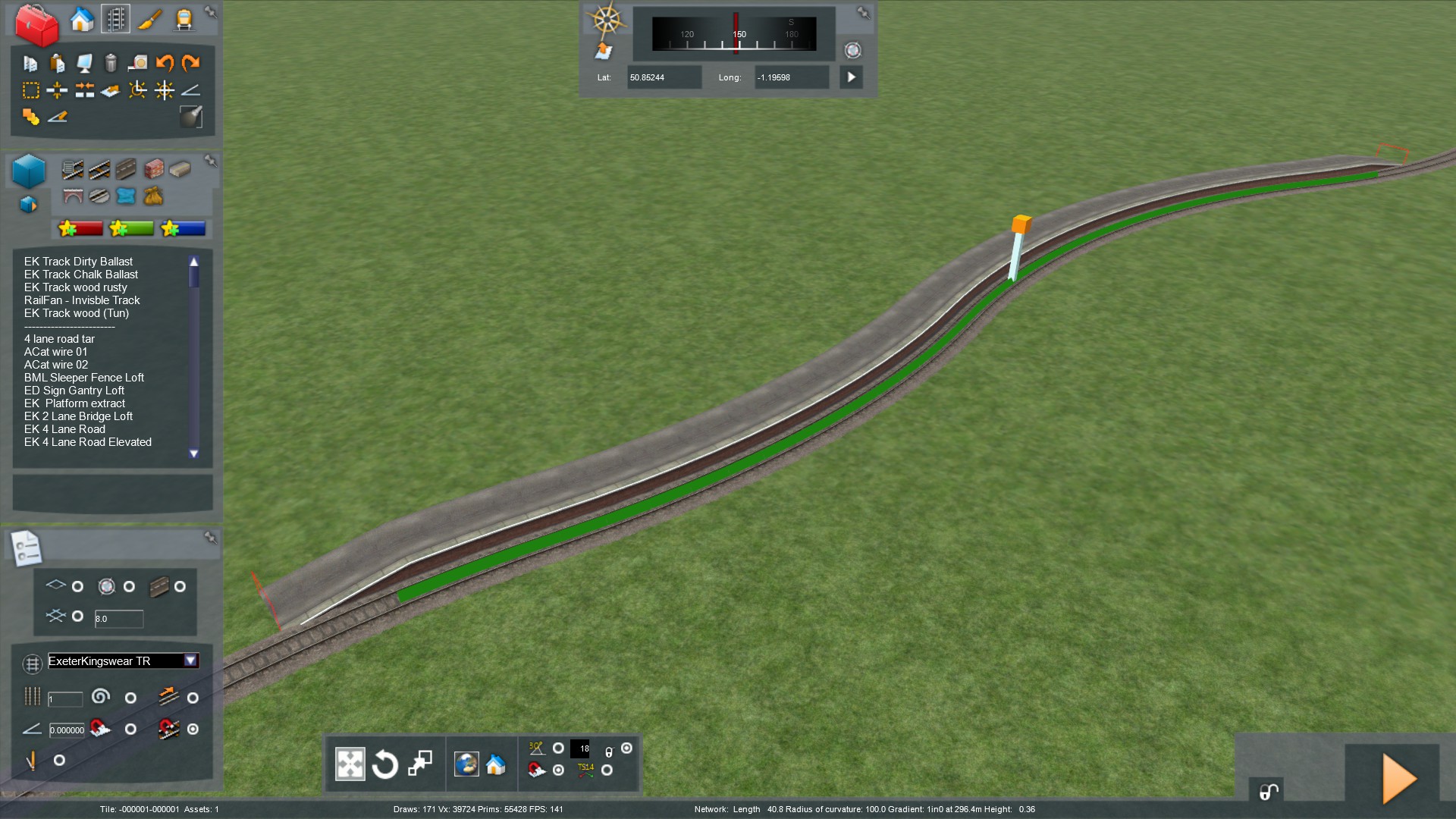
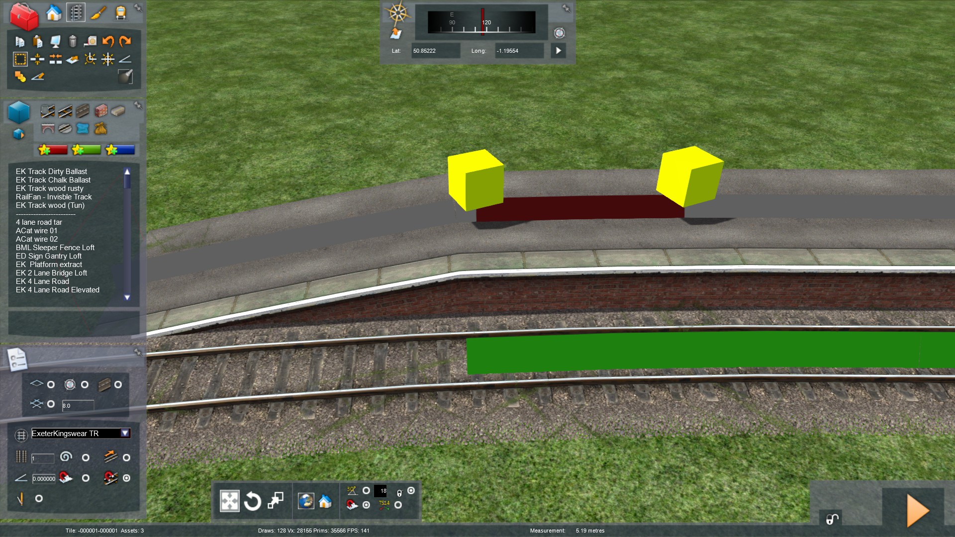
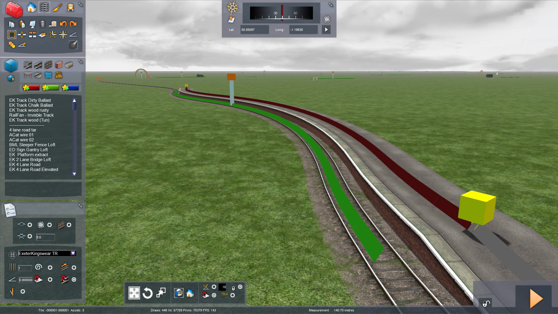
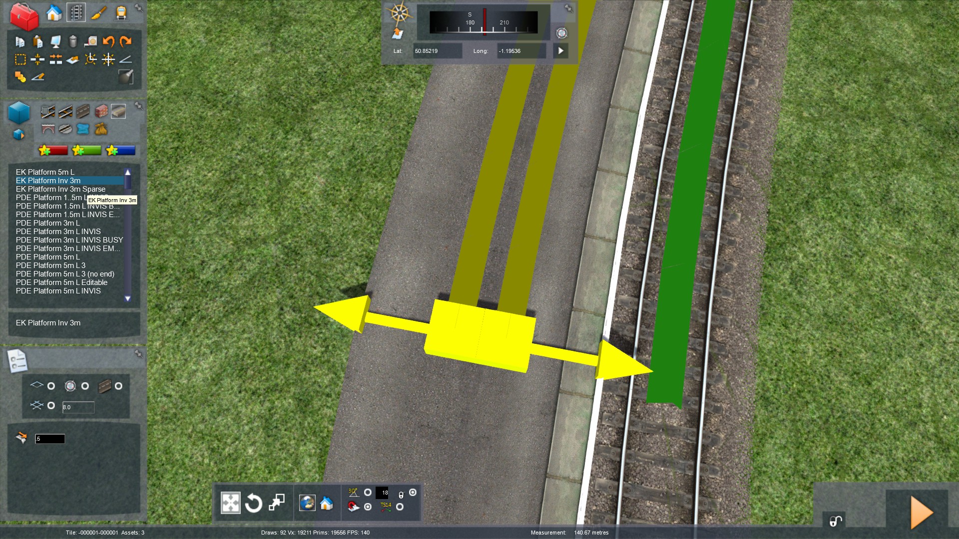
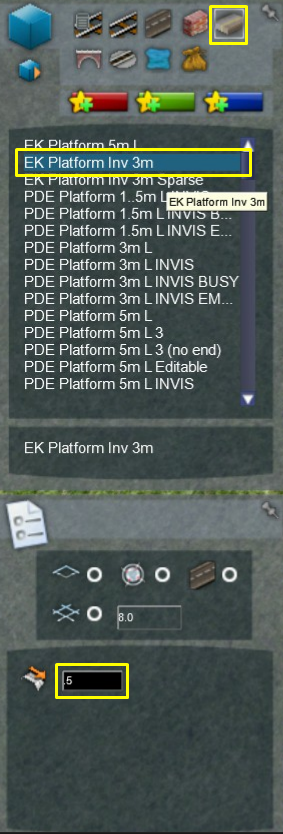
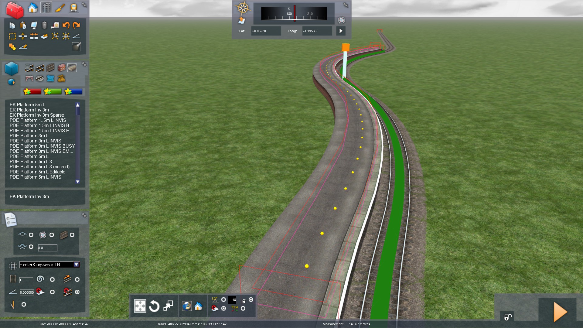
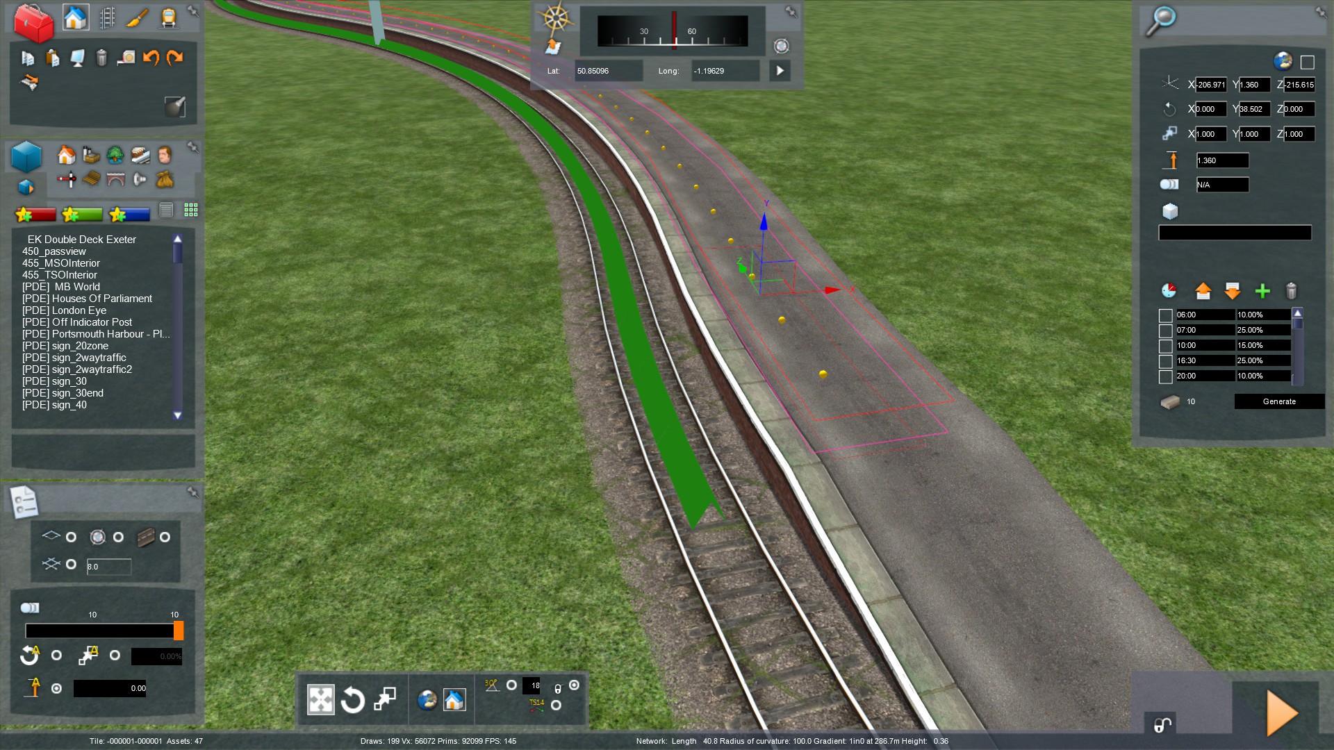
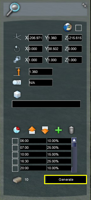
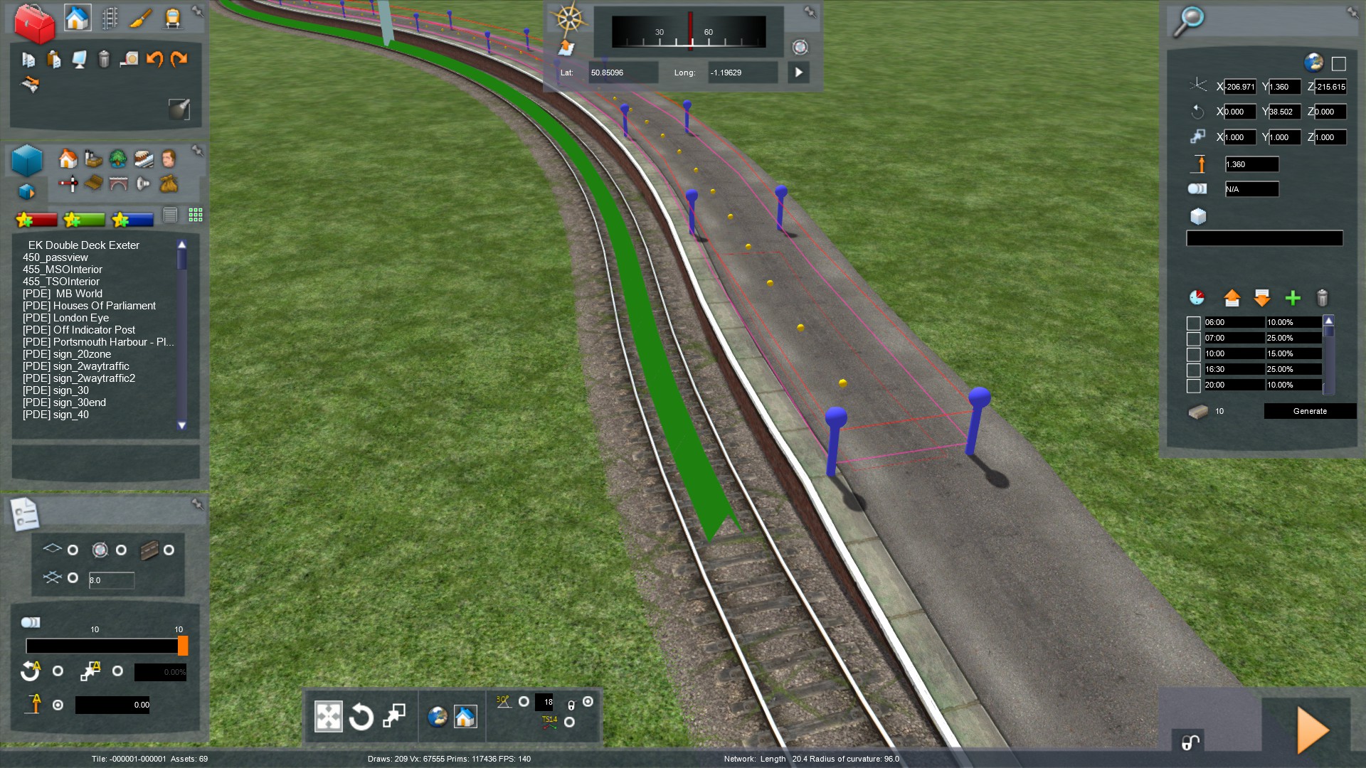
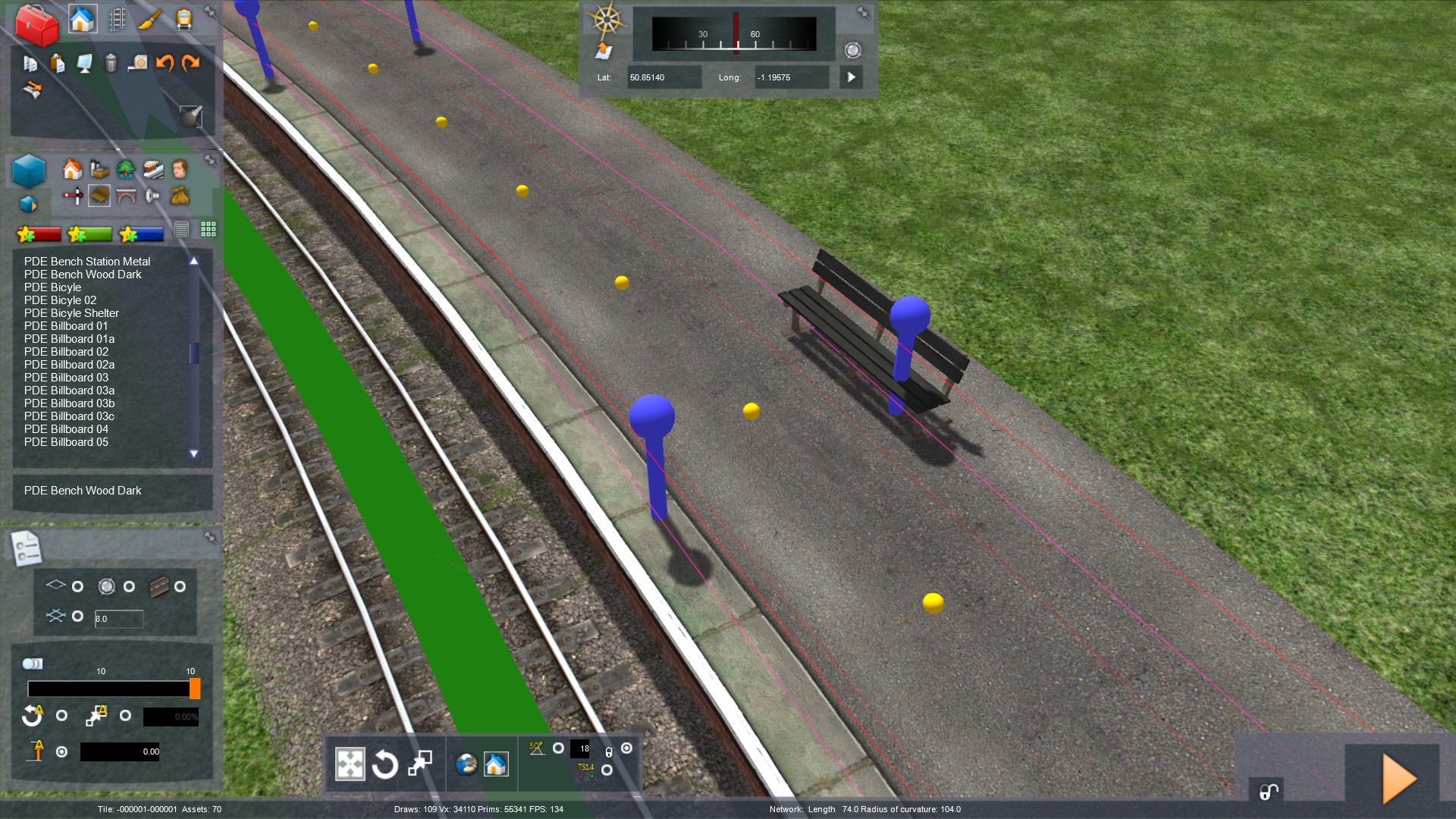
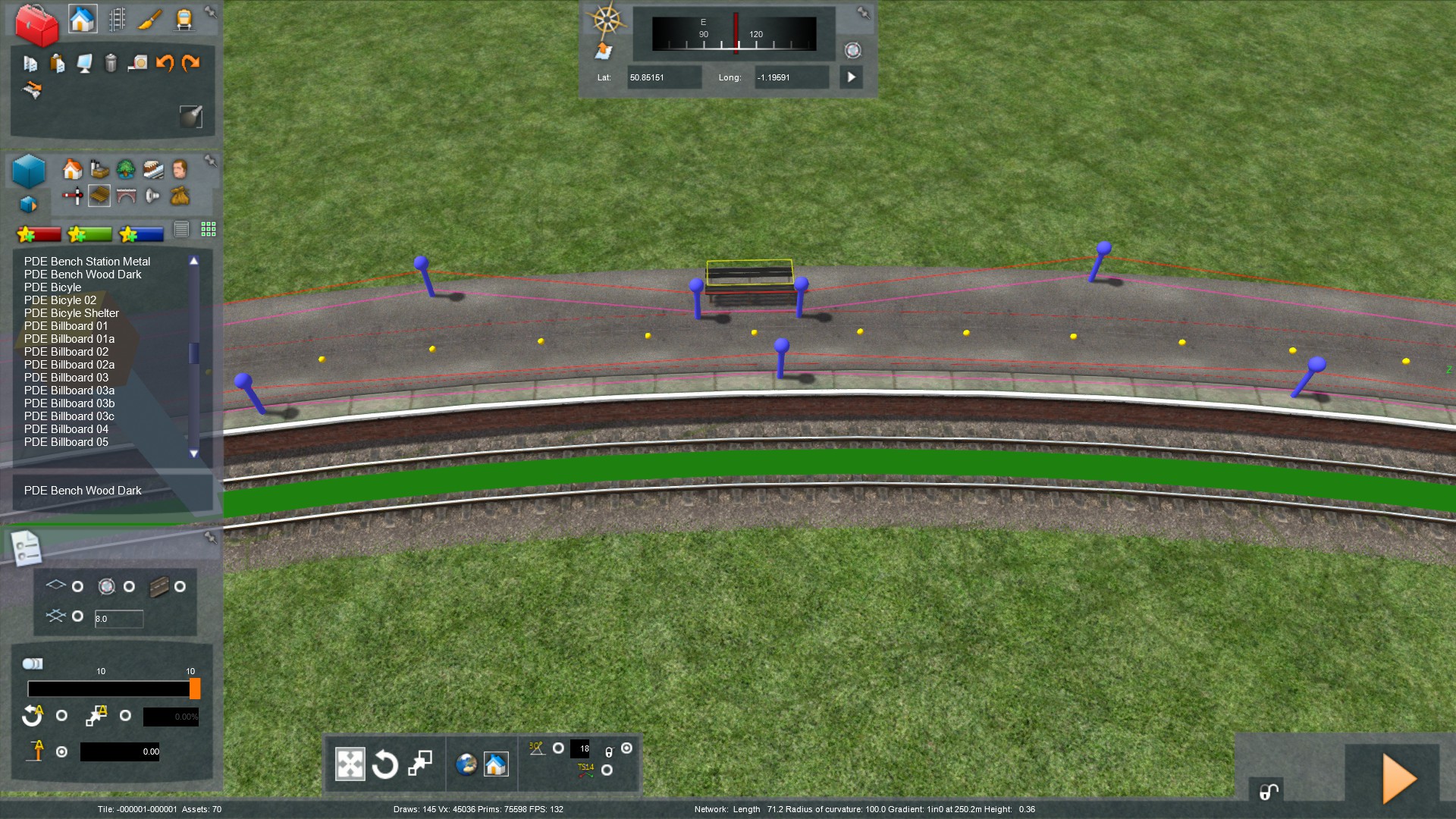
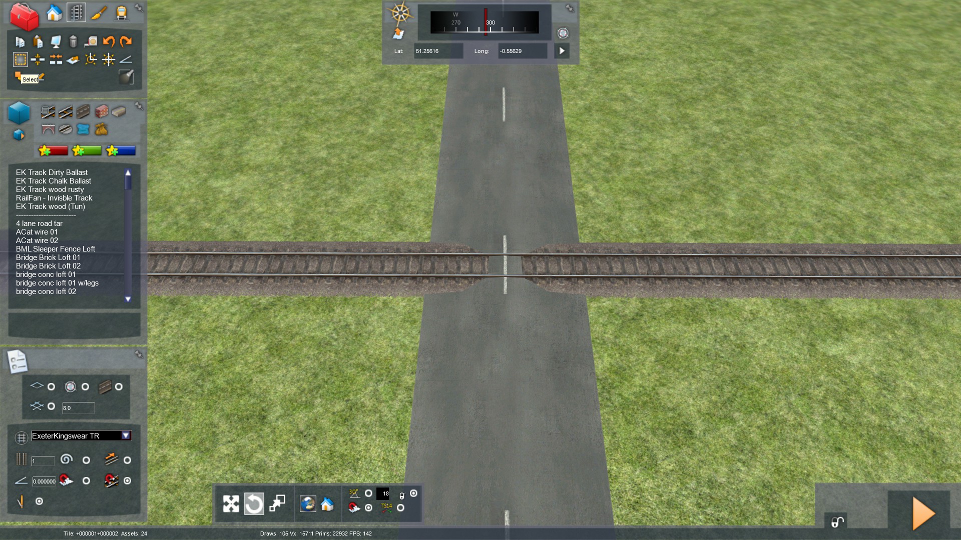
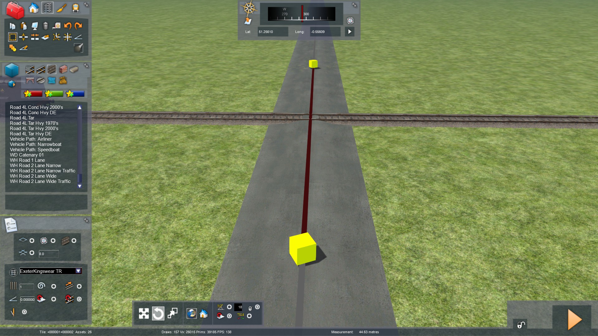
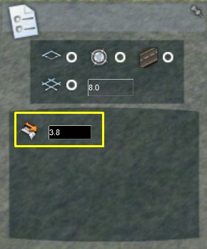
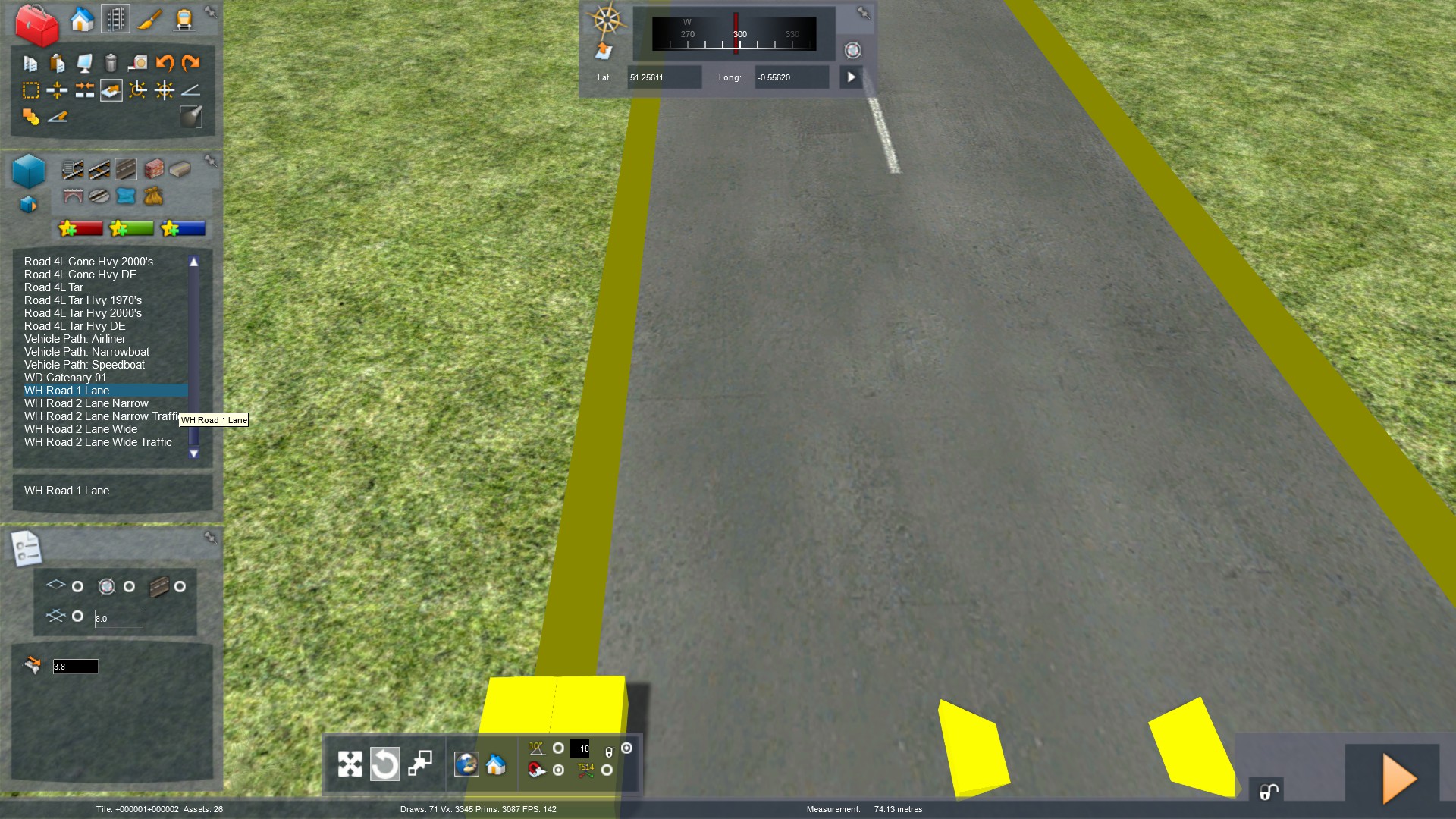
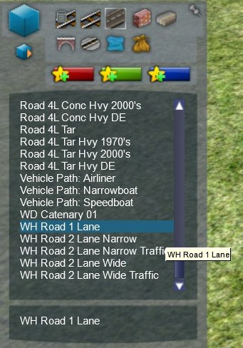
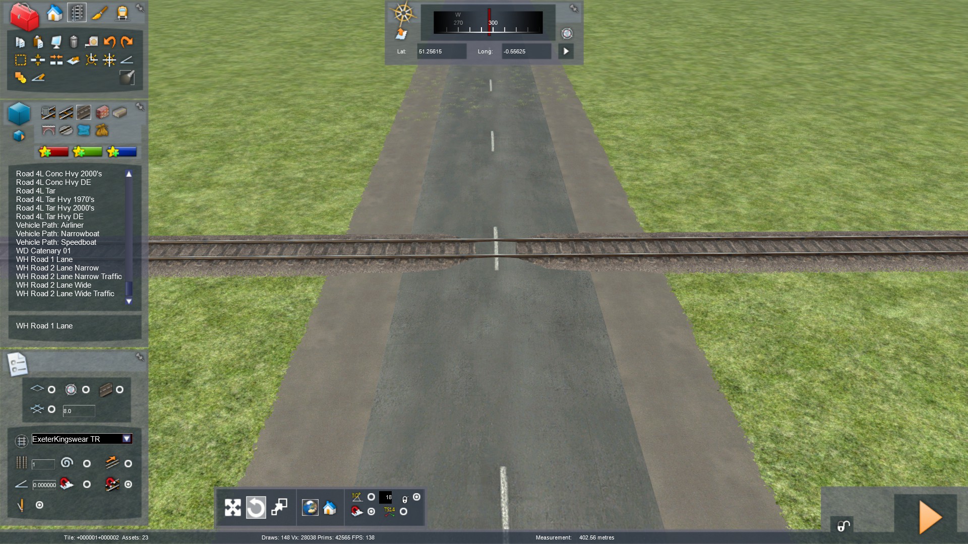
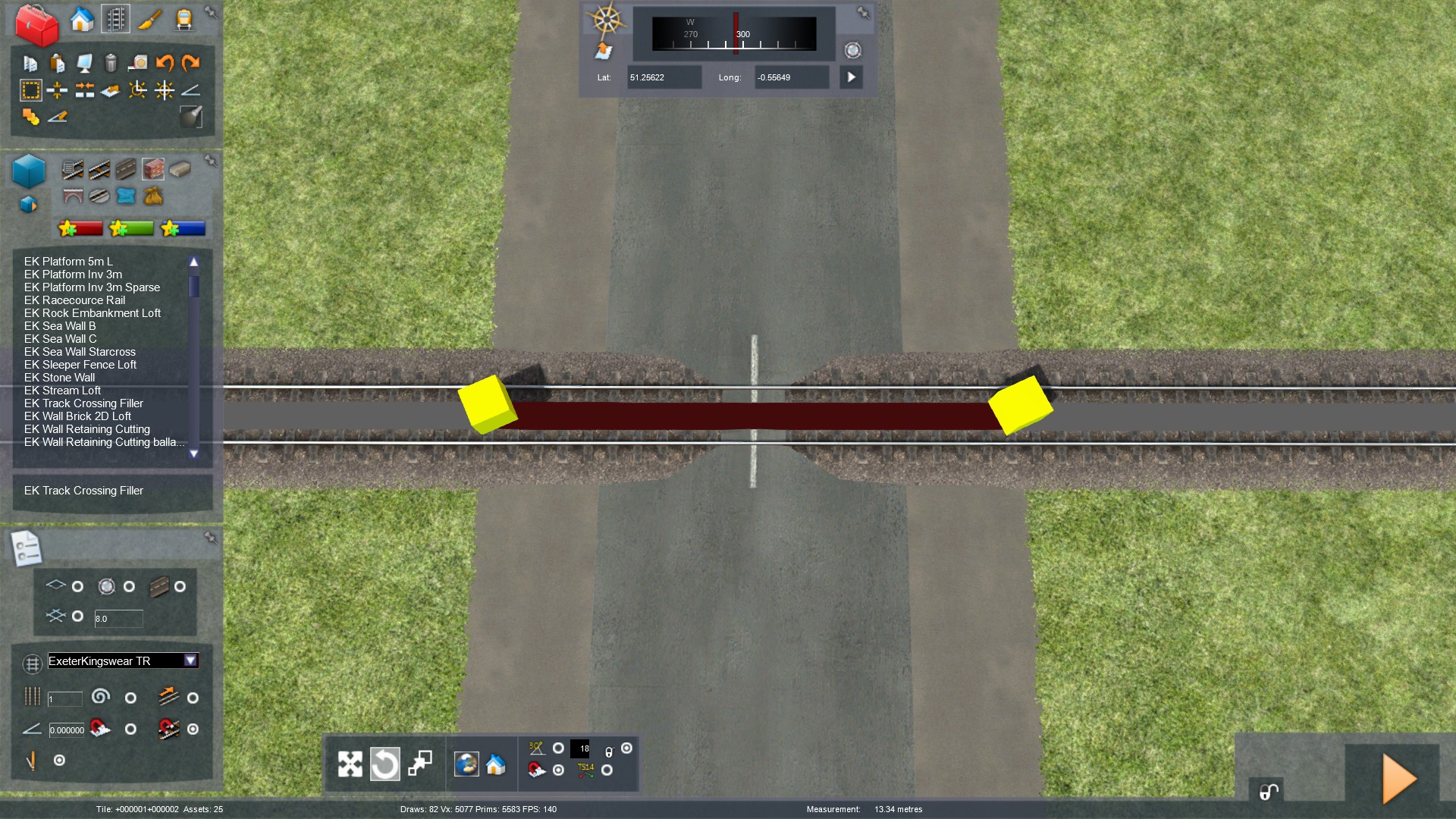
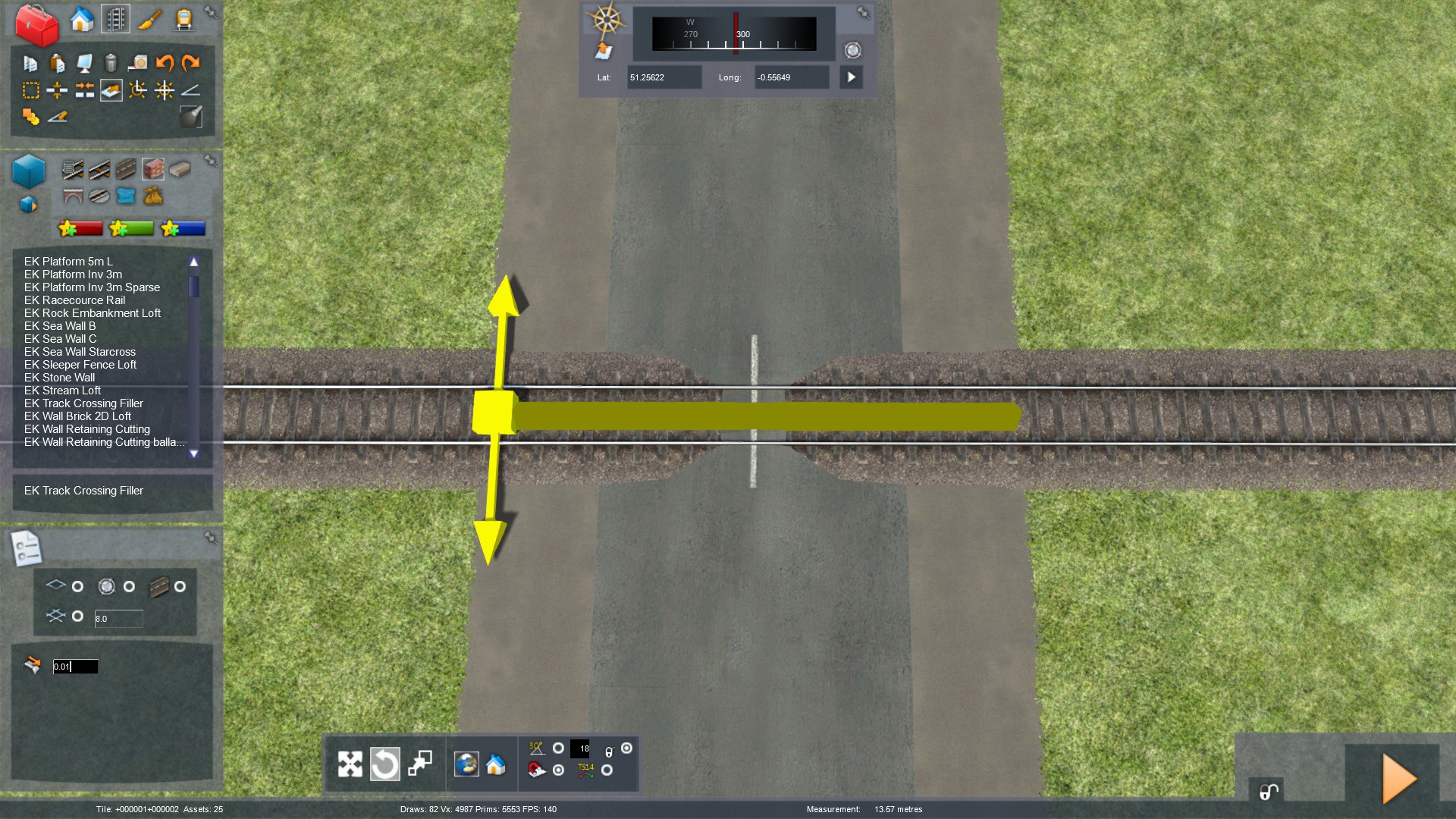
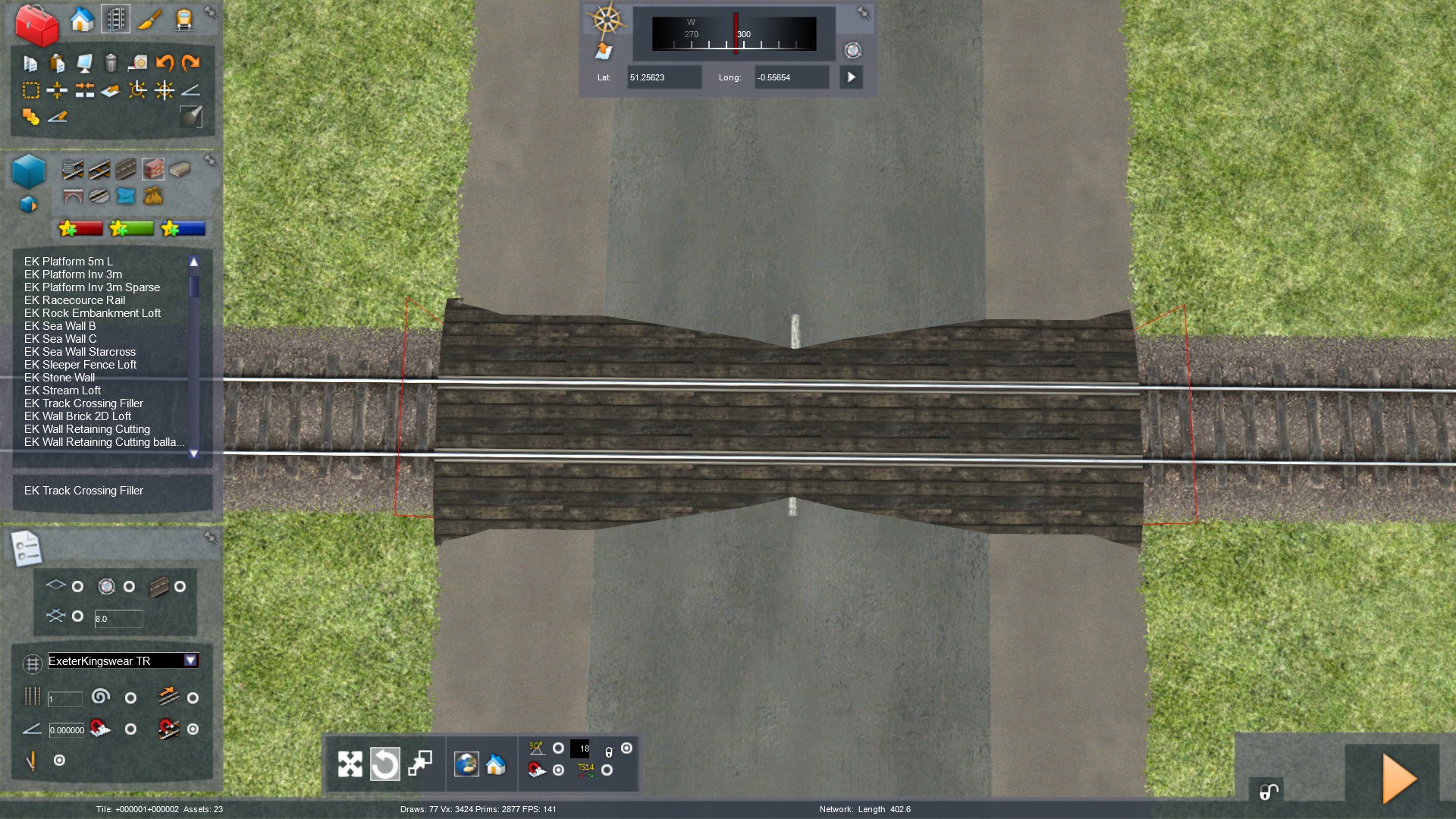
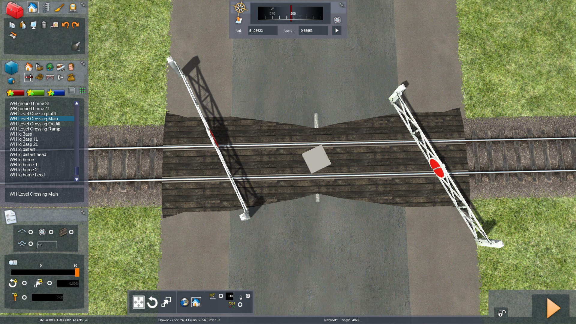
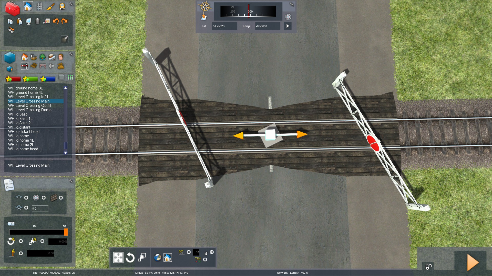
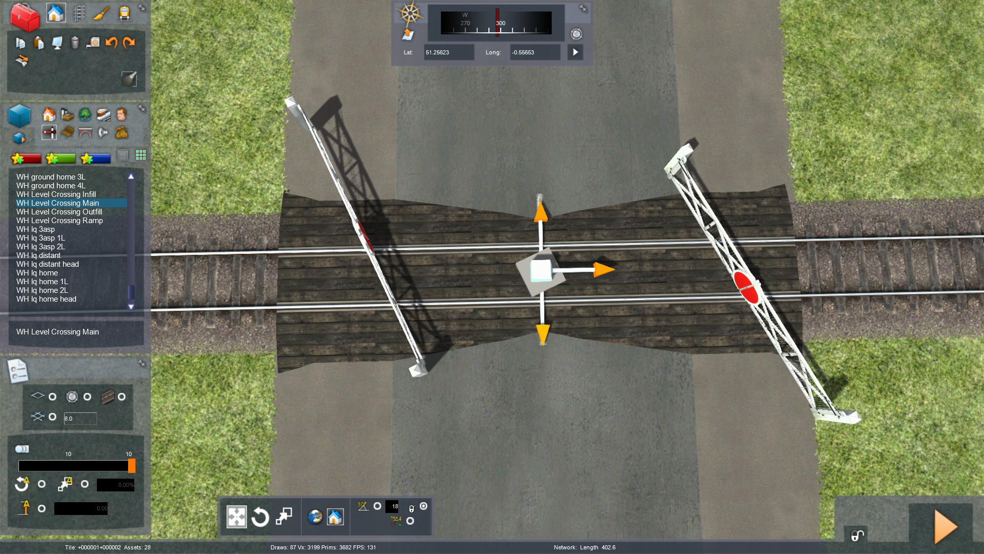
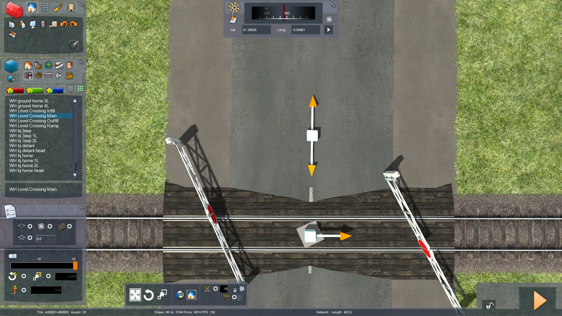
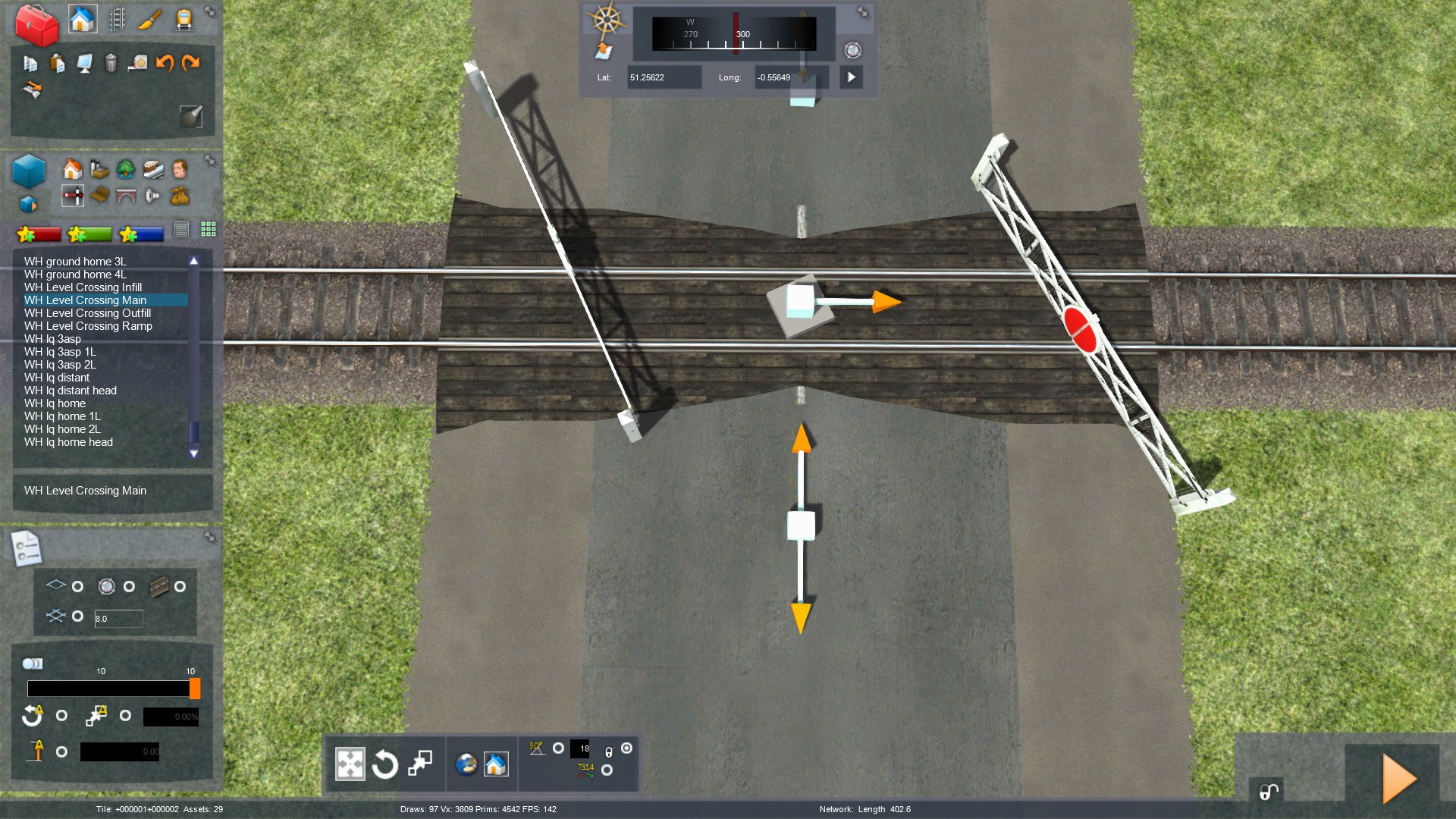
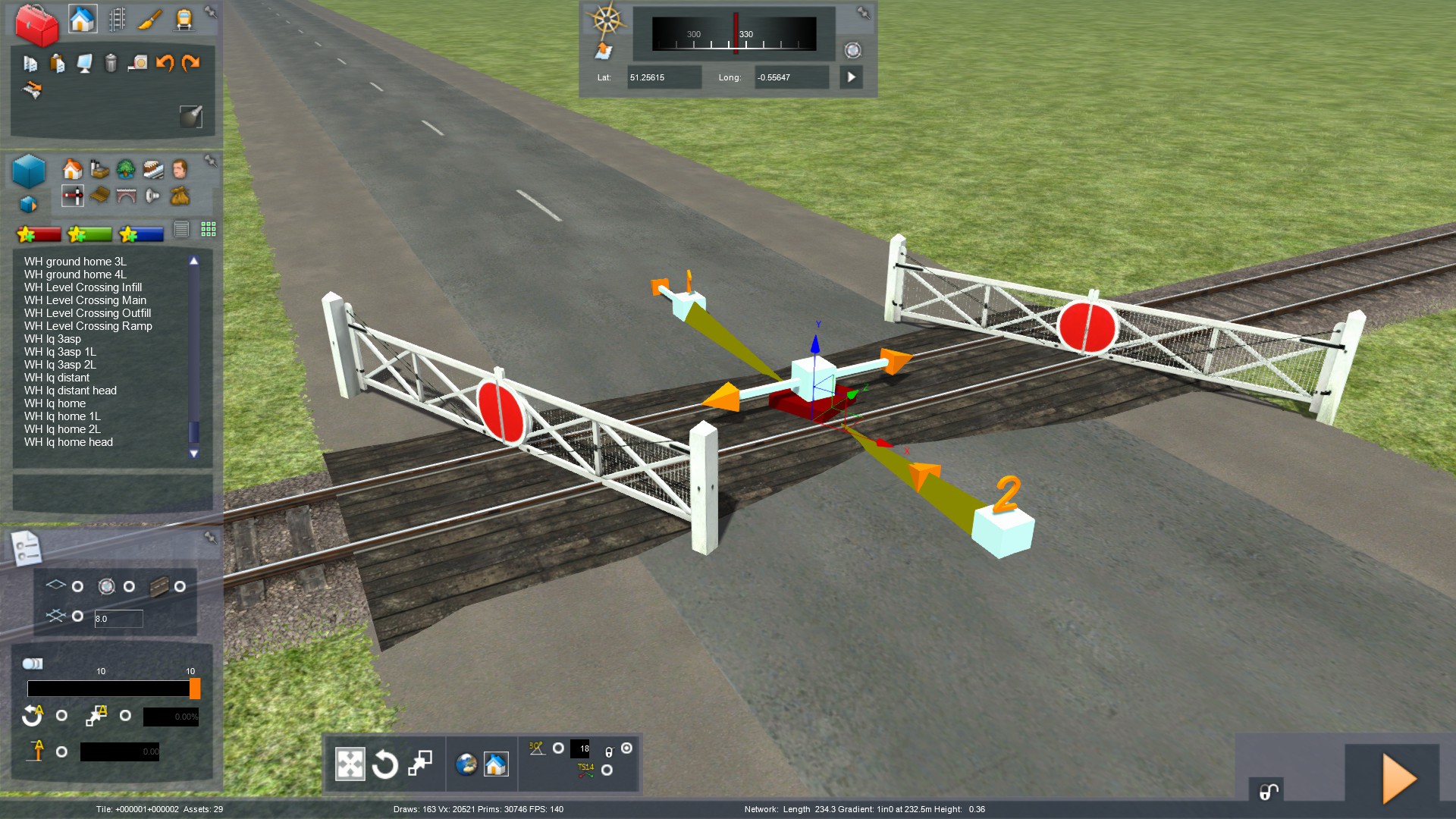
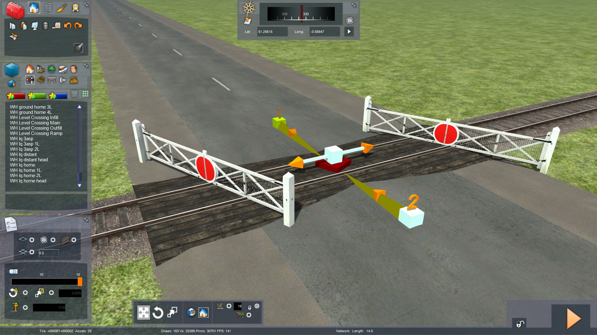
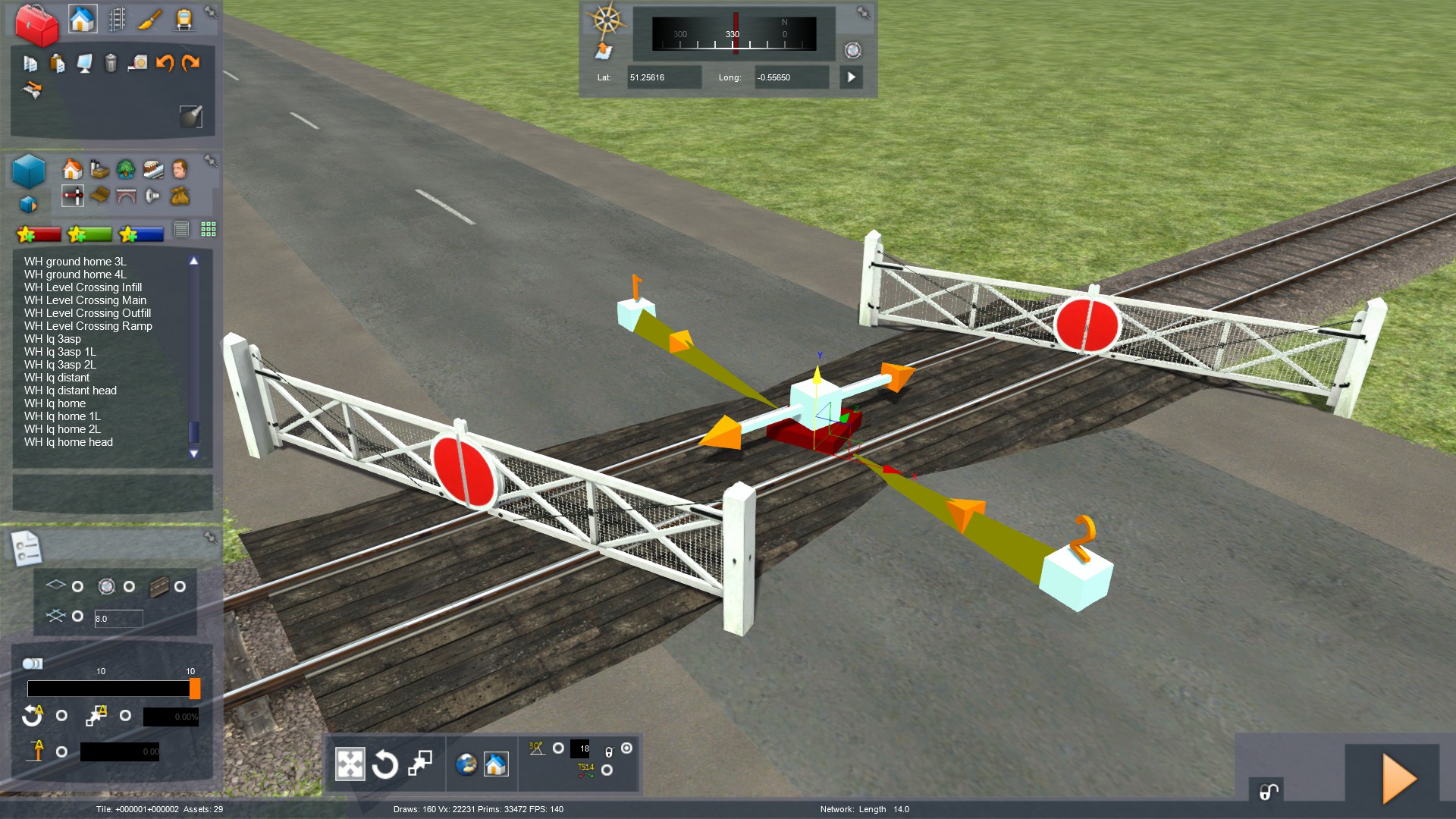
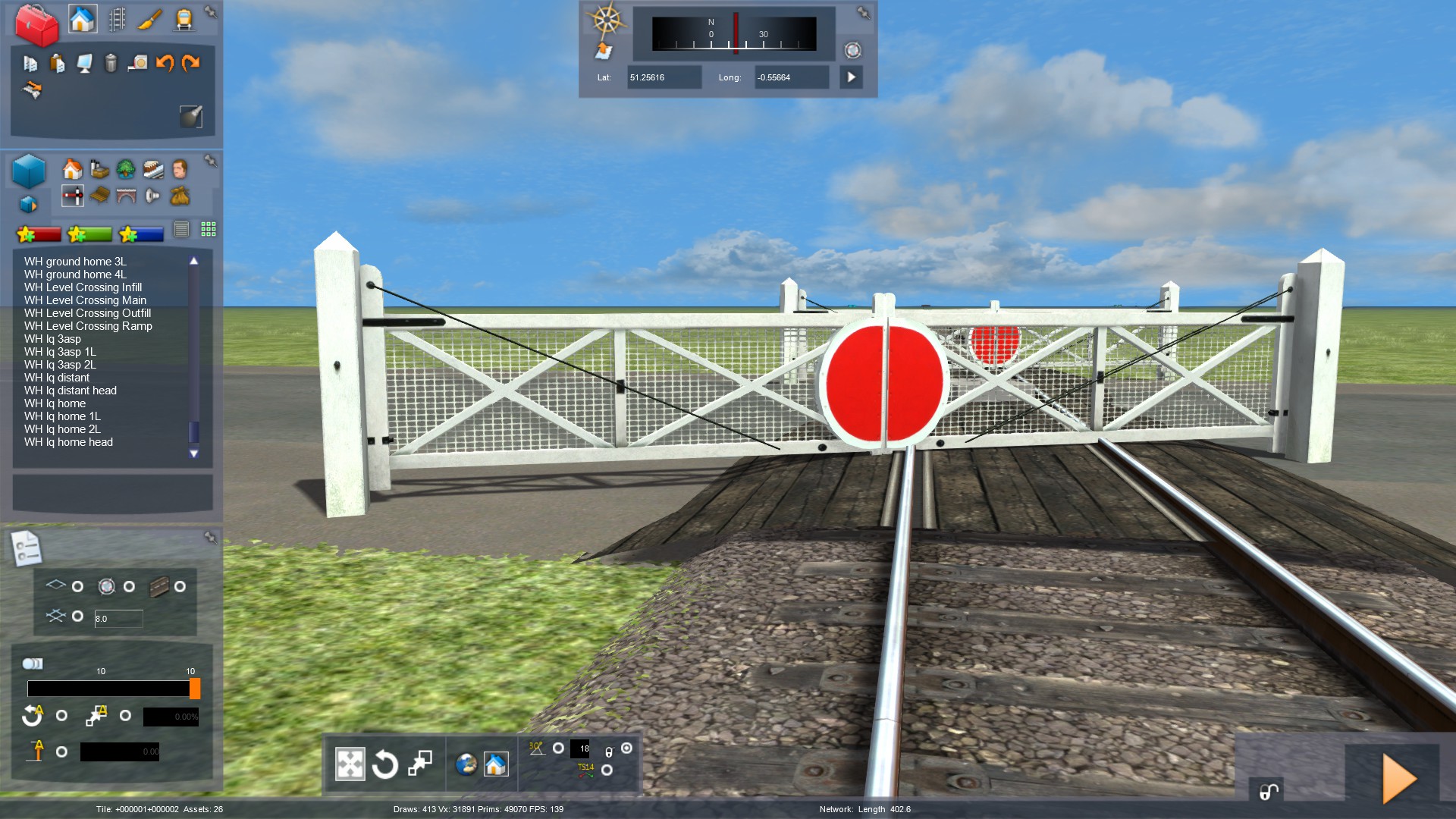
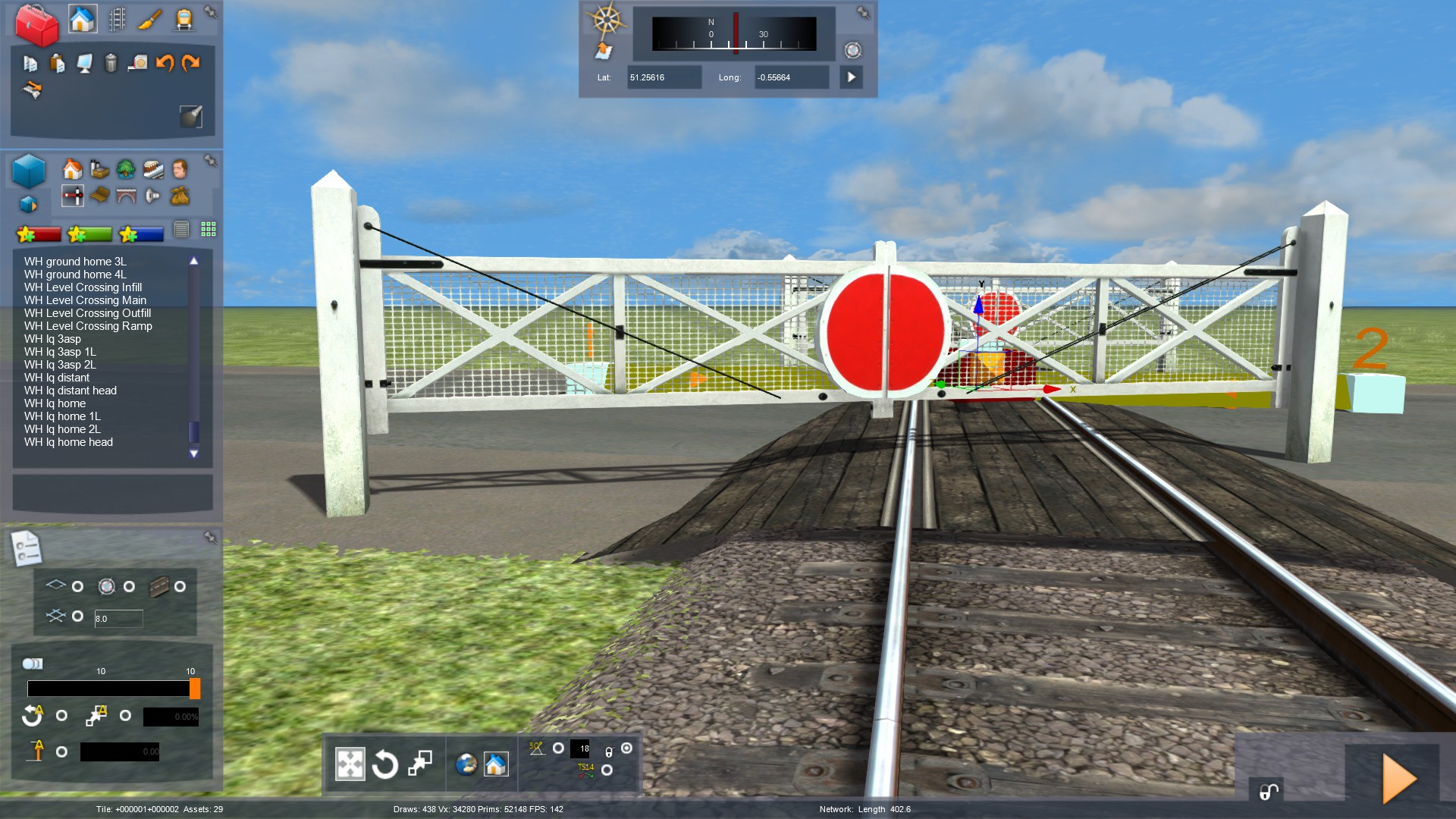
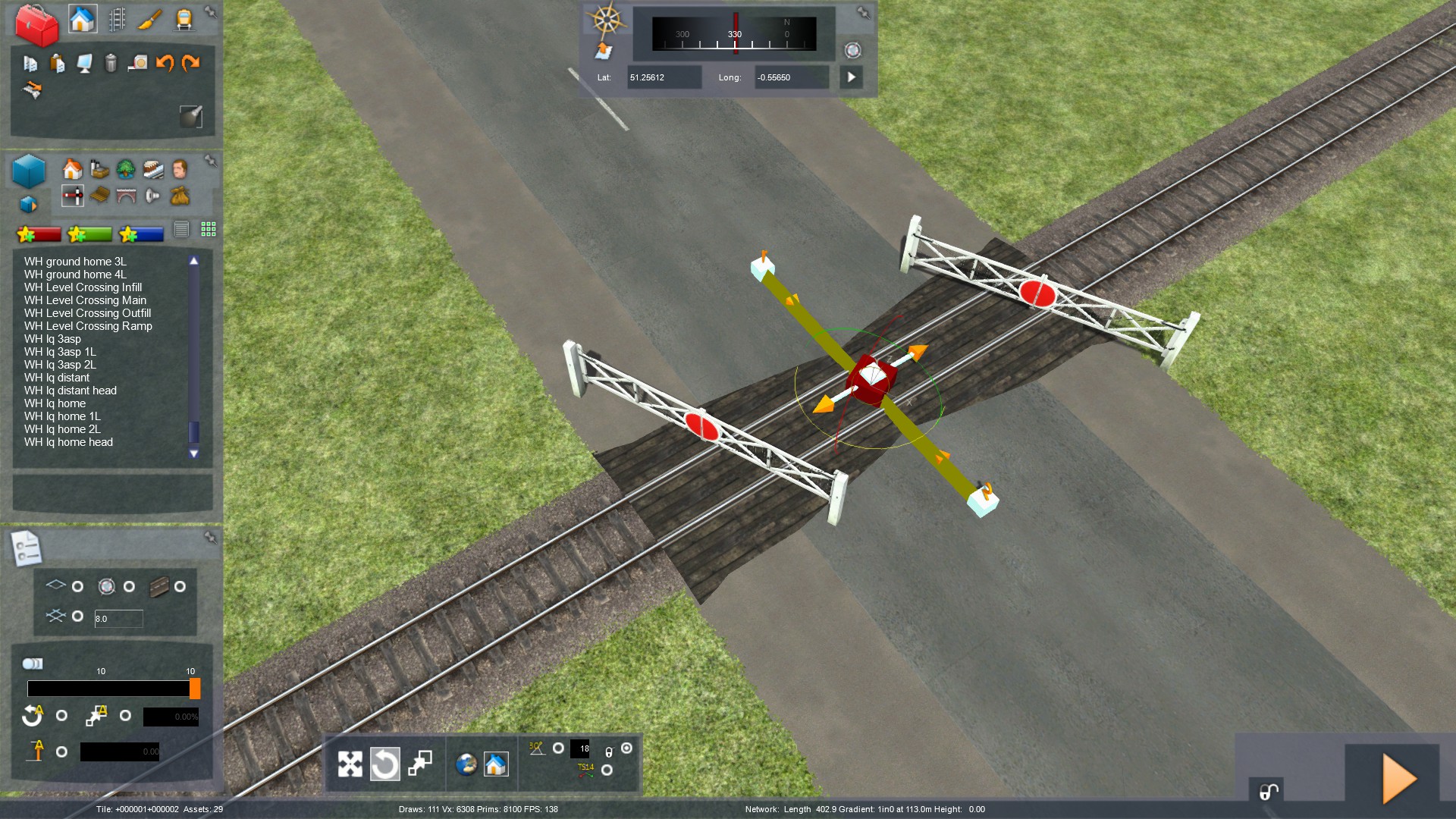
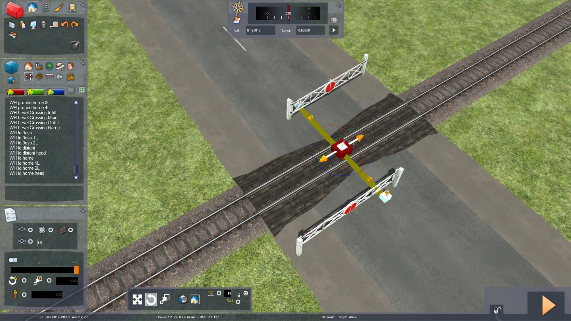
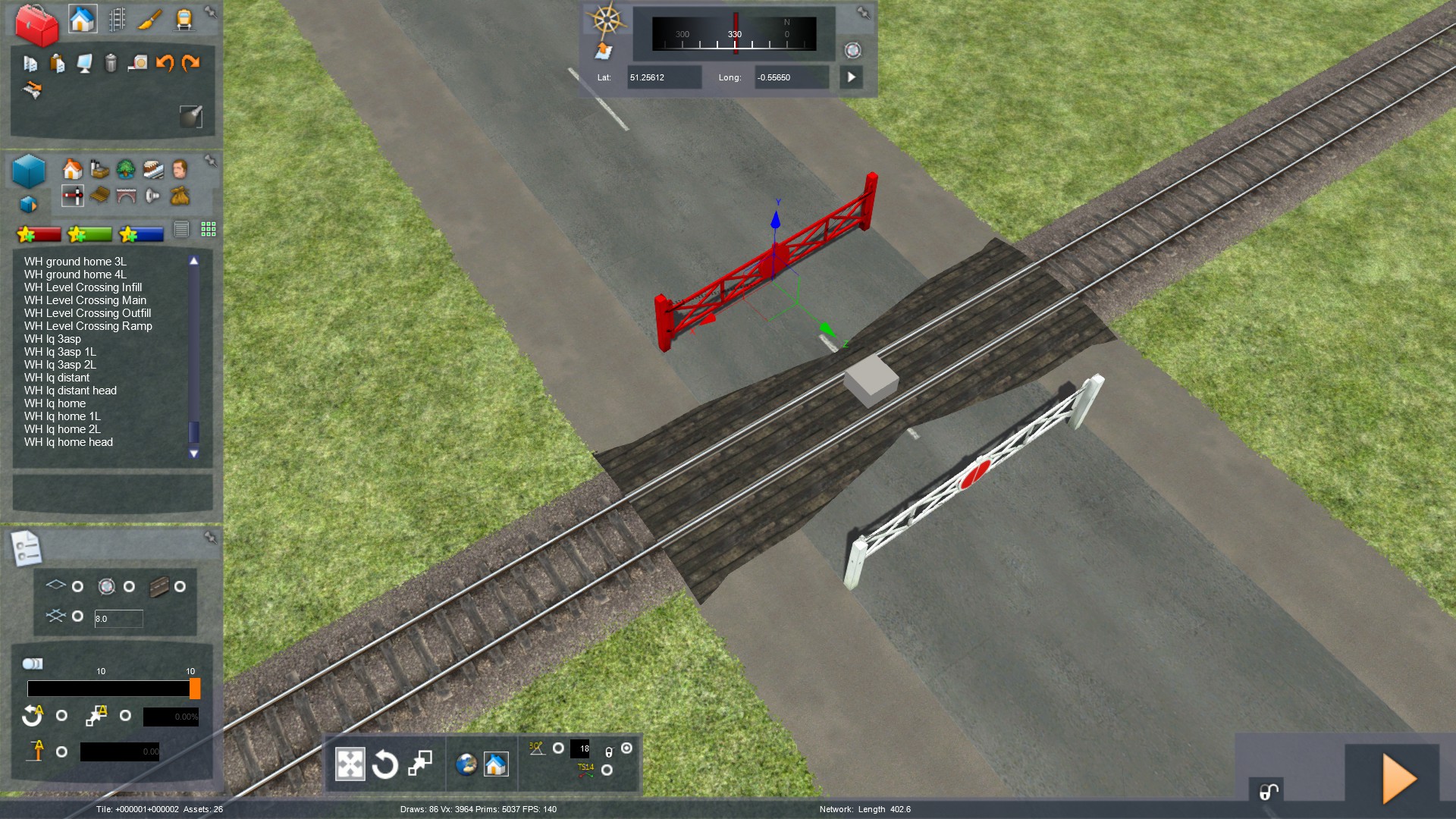
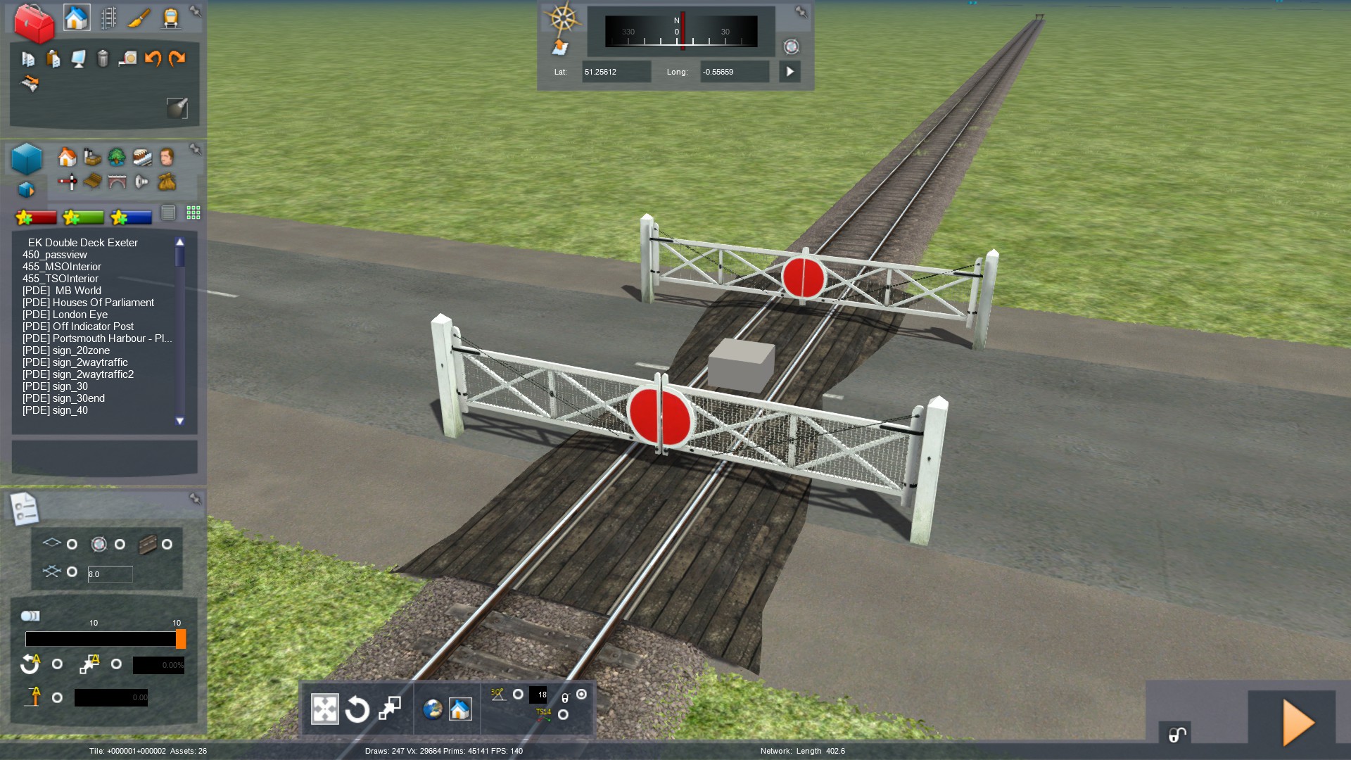
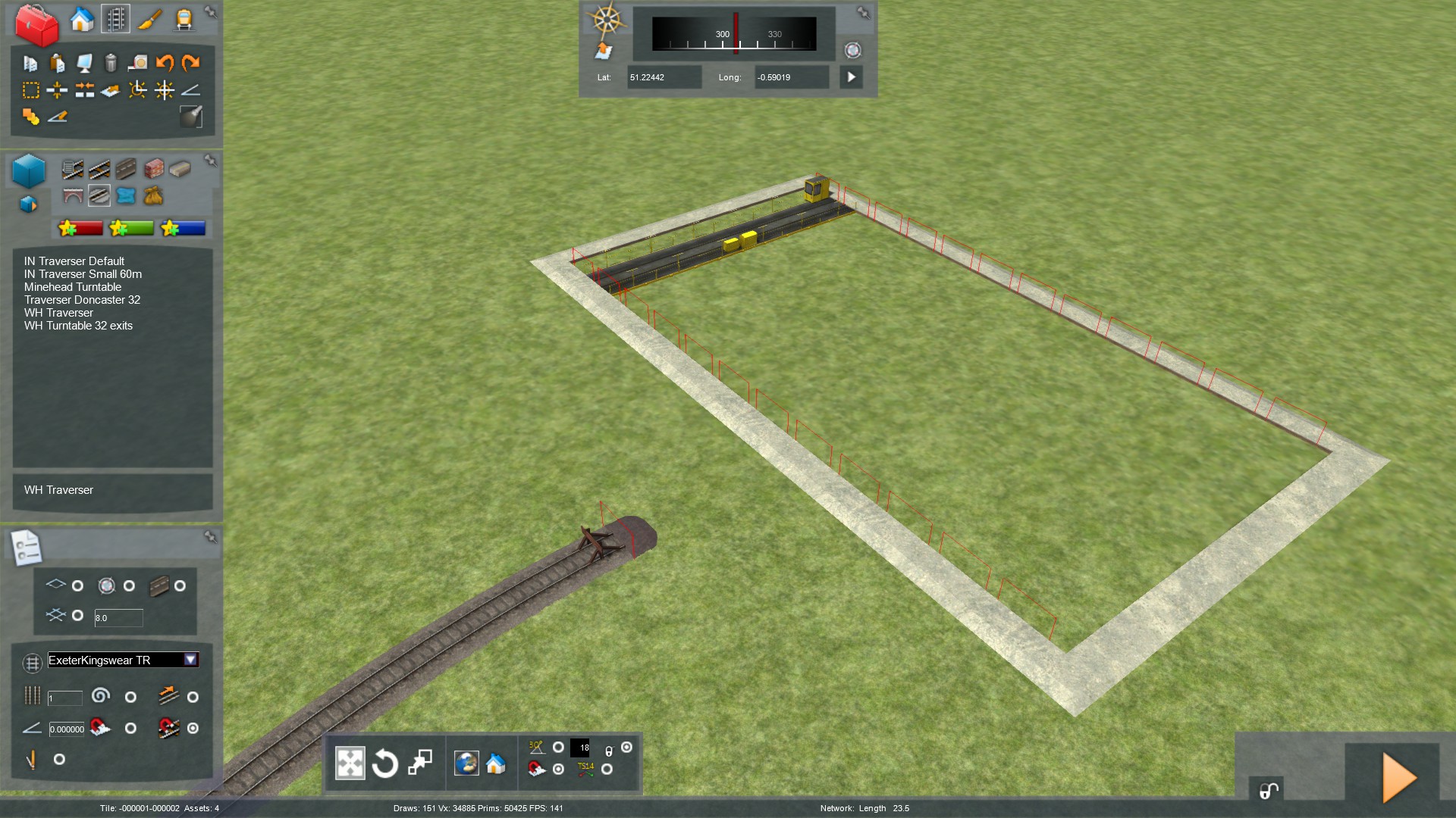
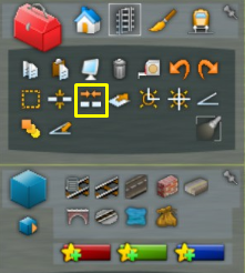
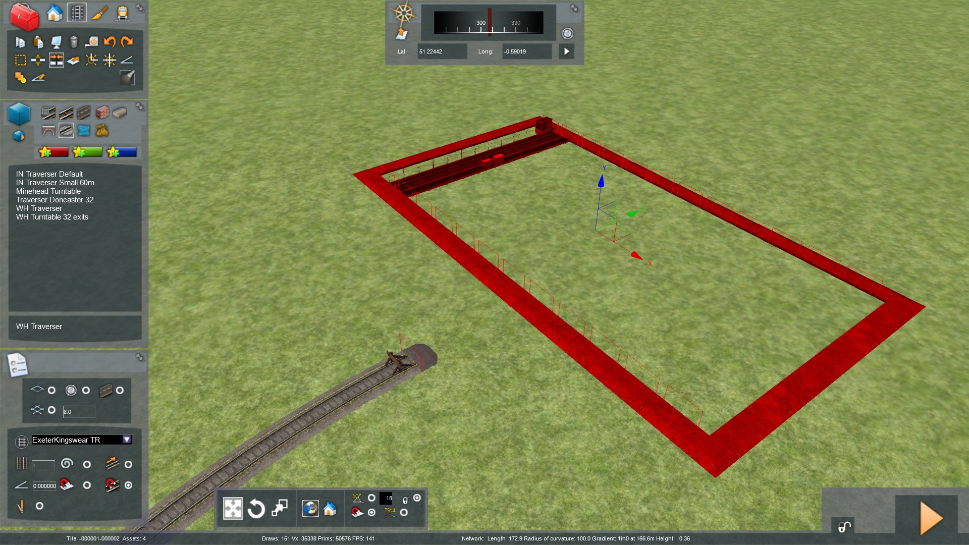
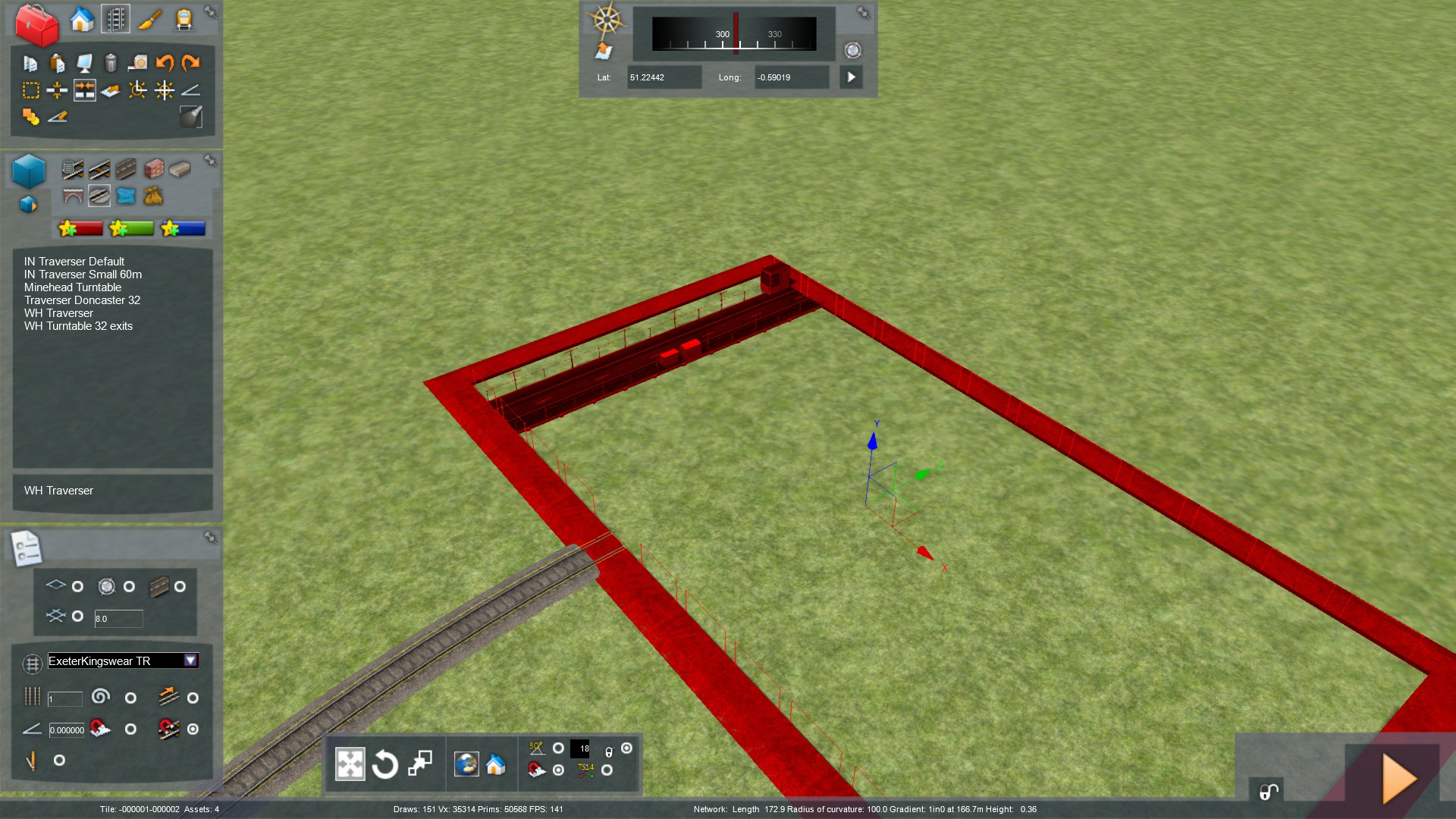
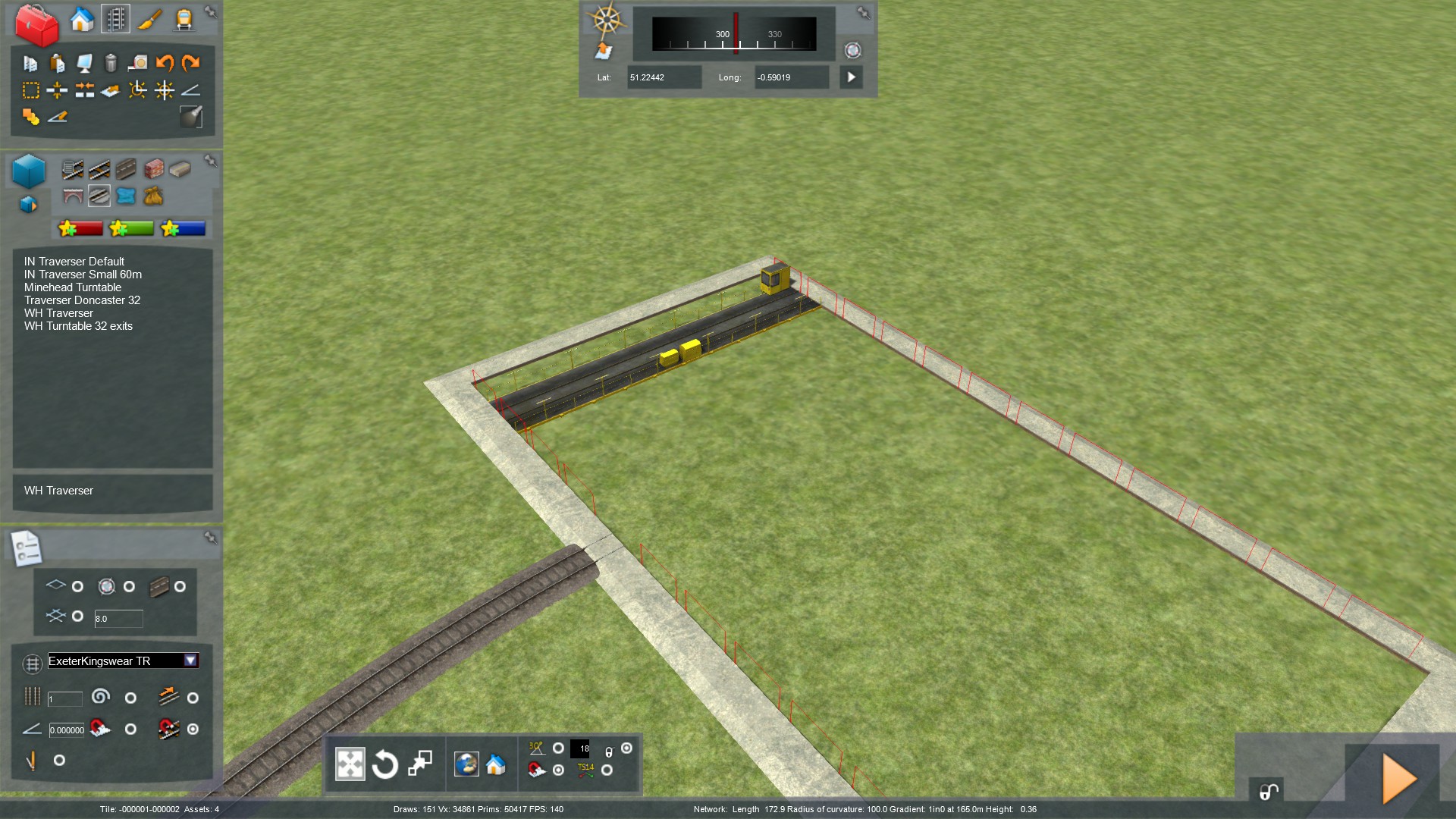
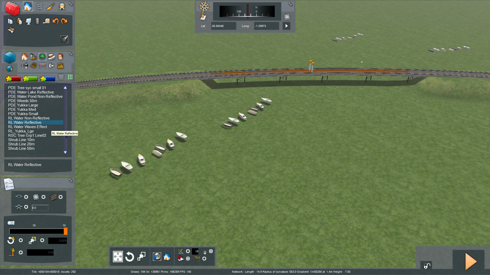
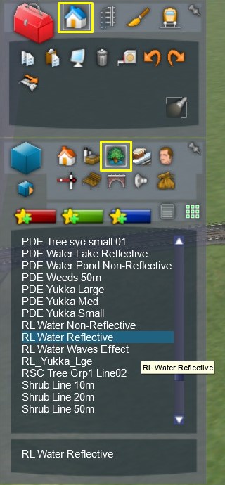
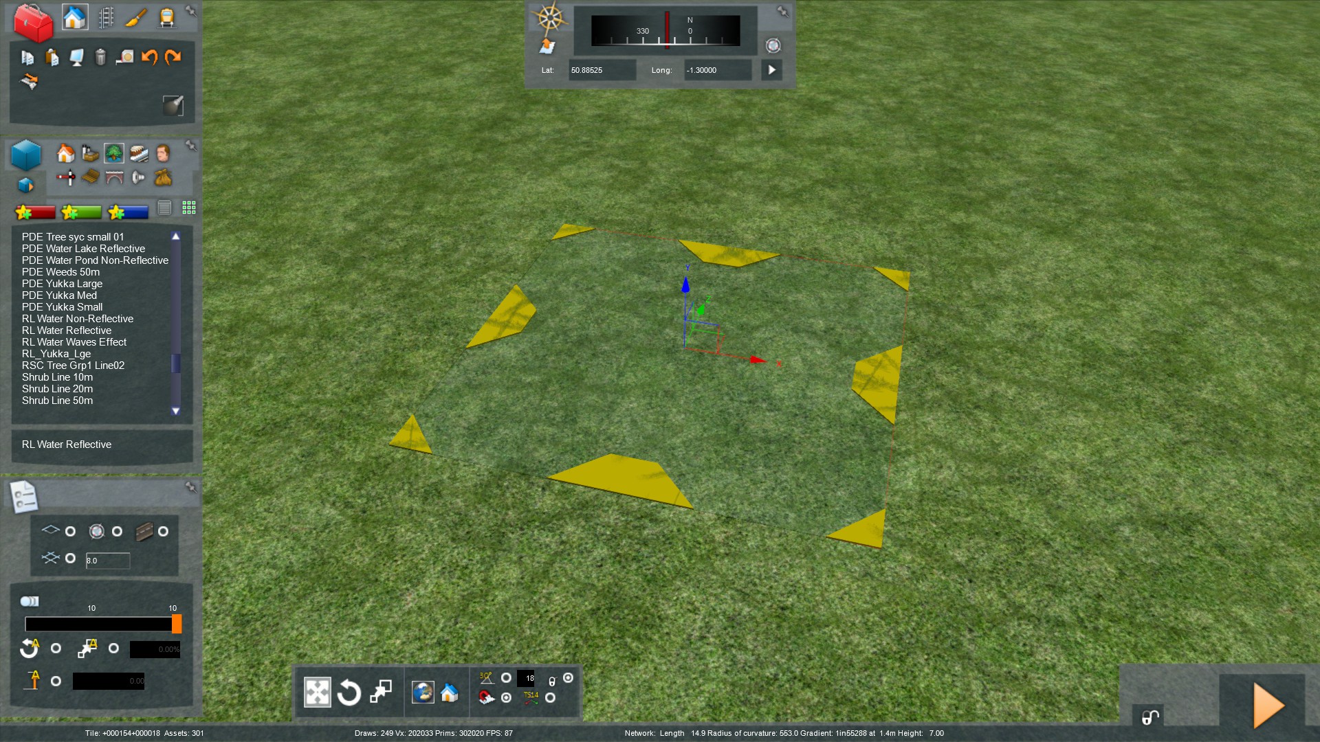
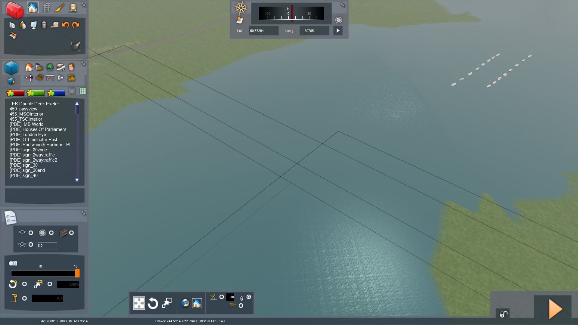
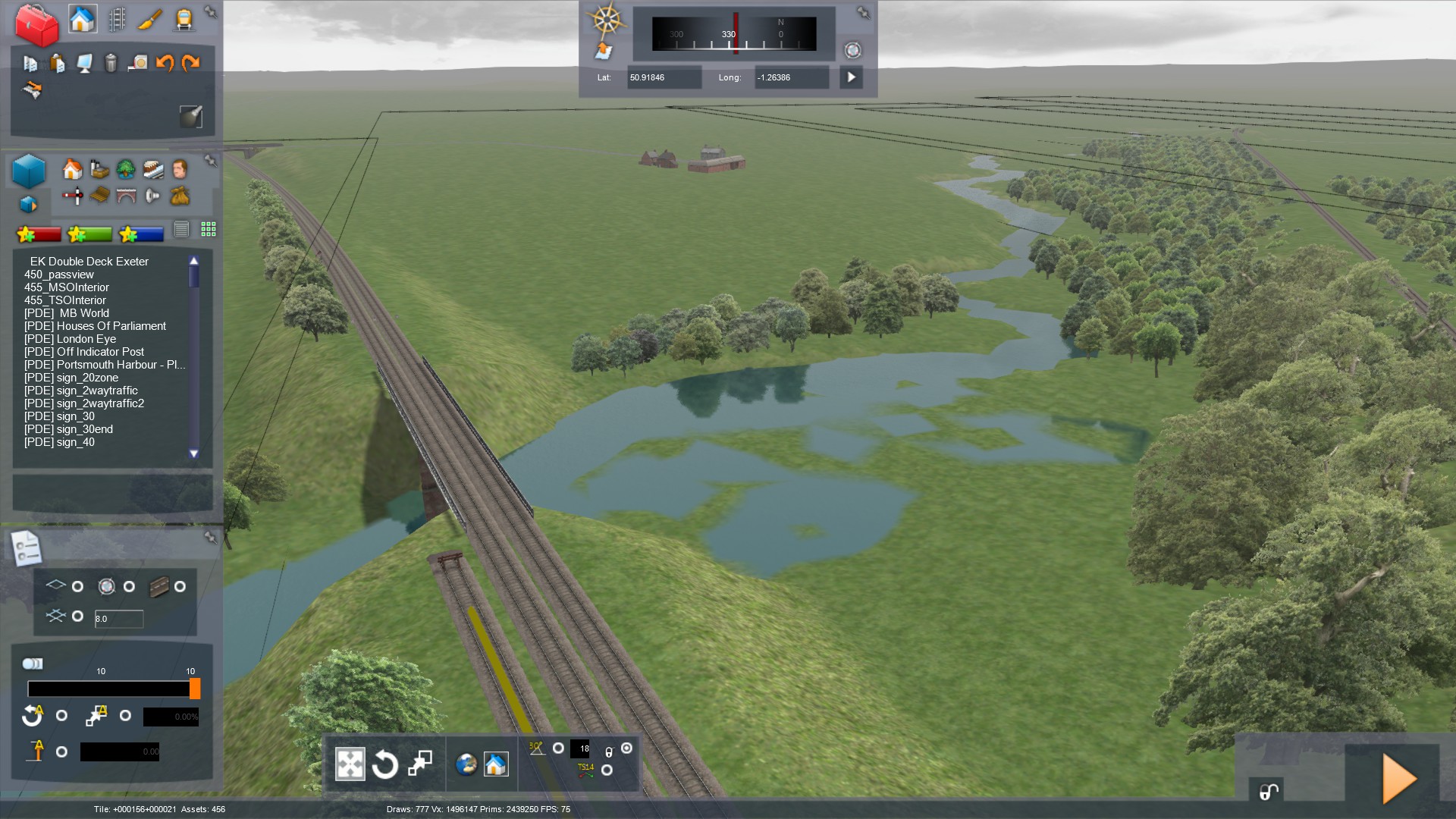
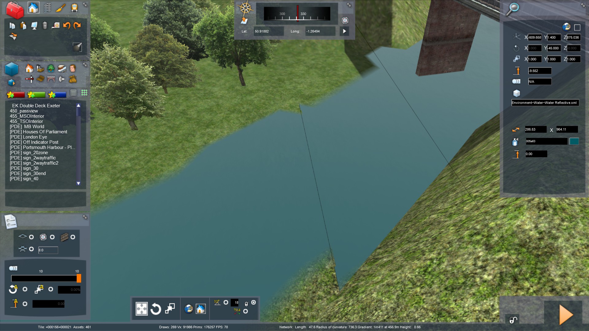
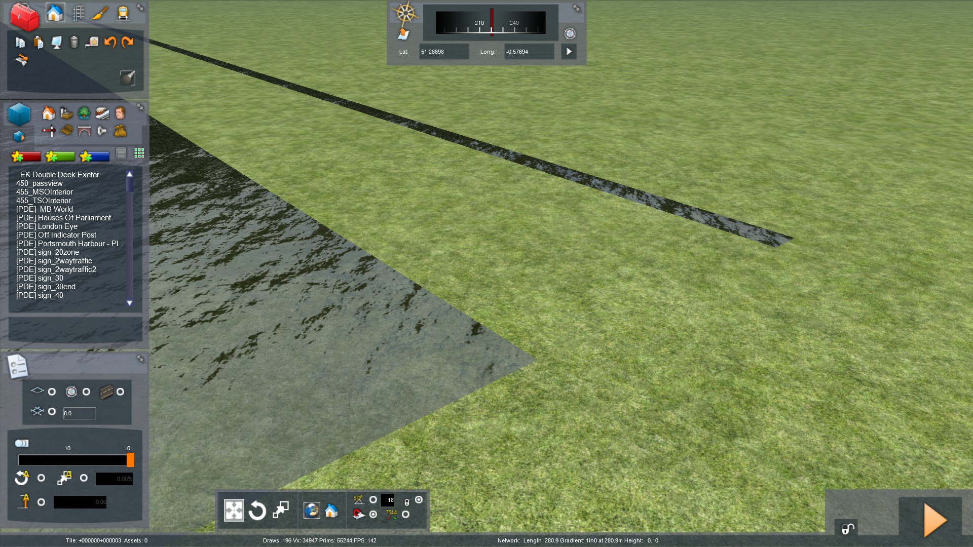
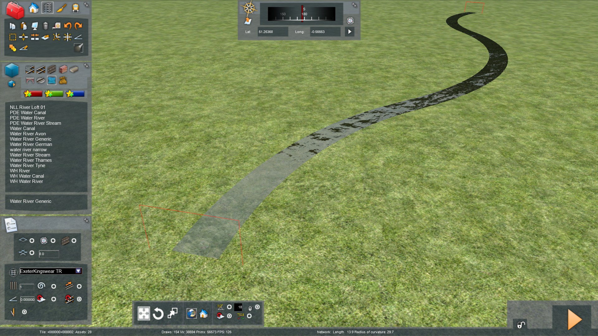
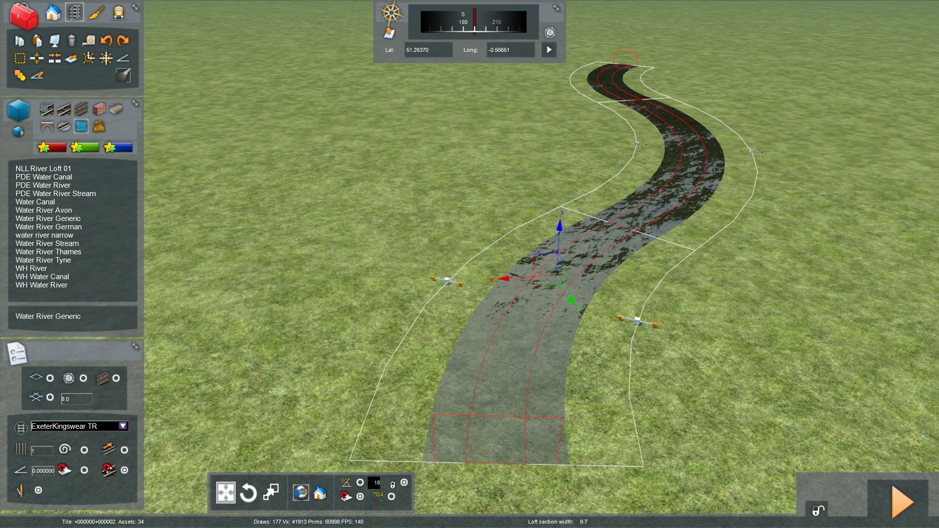
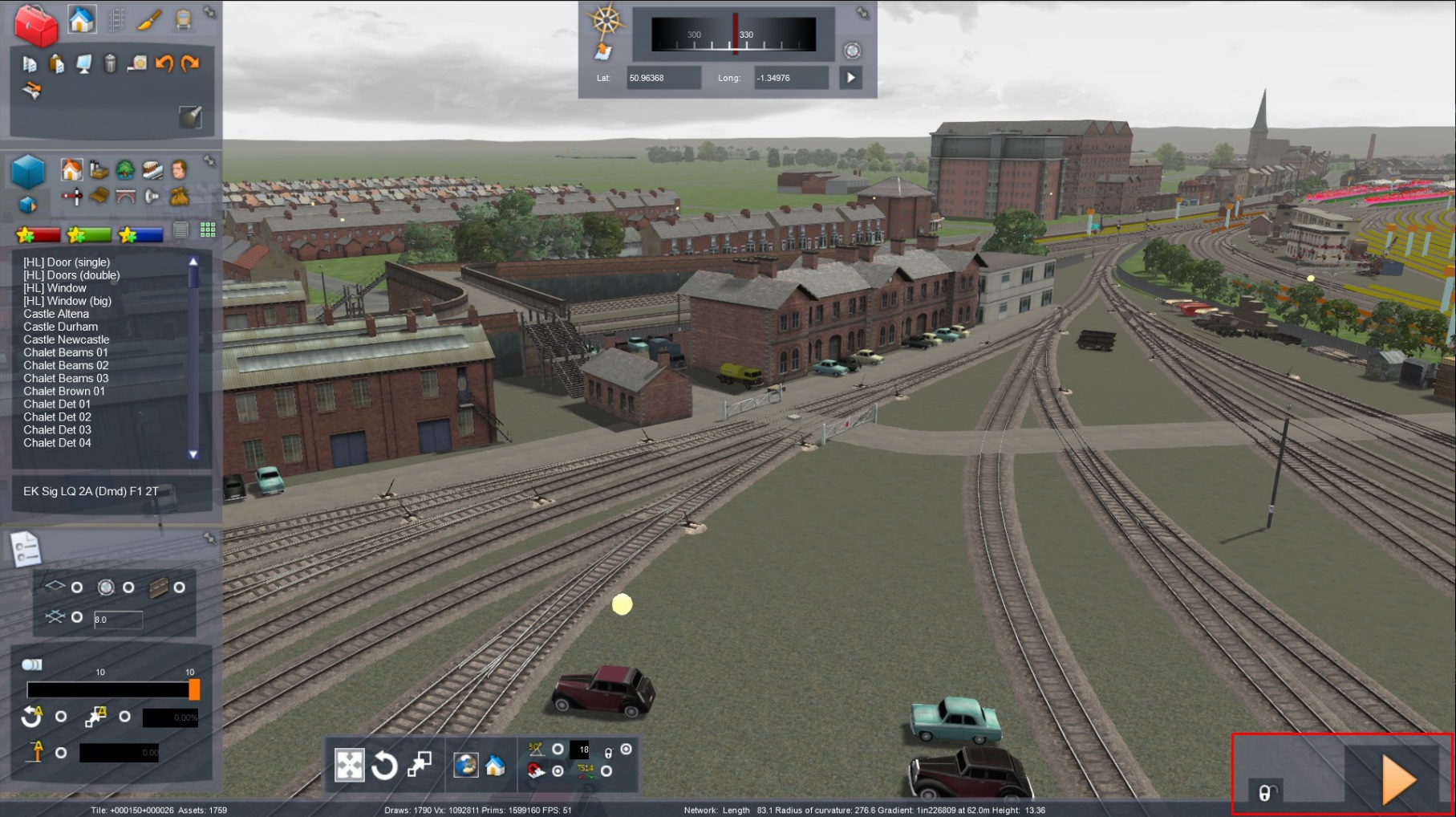
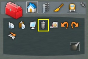
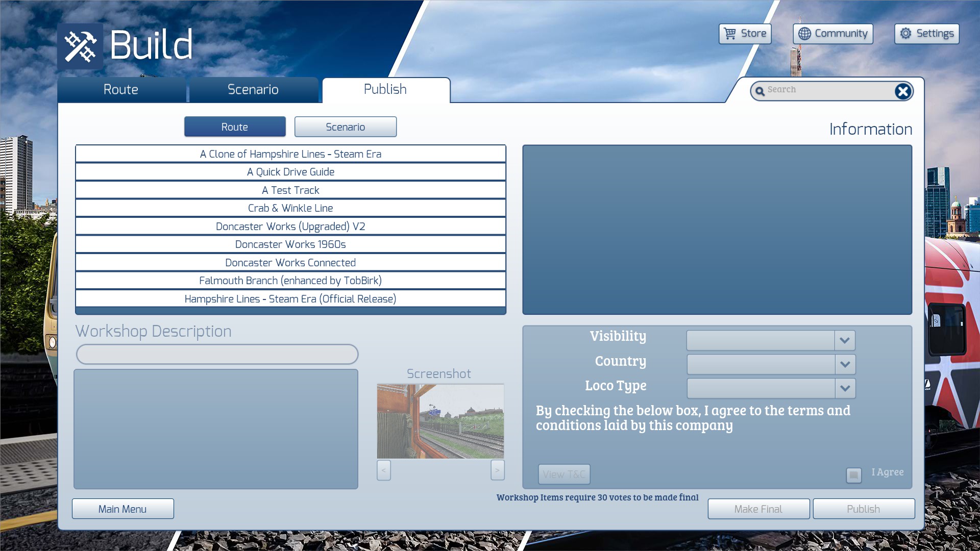
I advise you to use the World Editor, select all sections of track, and use the track properties dialogue to set the electrification property.
PF Singapore